Isolated direct-current boost converter of two-phase parallel boost circuit and control method of isolated direct-current boost converter

A step-up circuit and DC step-up technology, which is applied in the direction of converting DC power input to DC power output, adjusting electrical variables, and controlling/regulating systems. High power density, high efficiency, low power density and other issues, to achieve the effect of eliminating voltage spikes, high switching frequency, and high power density

Pending Publication Date: 2022-06-03
INST OF ELECTRICAL ENG CHINESE ACAD OF SCI
View PDF0 Cites 0 Cited by
  • Summary
  • Abstract
  • Description
  • Claims
  • Application Information

AI Technical Summary

Problems solved by technology

[0005] In order to solve the above-mentioned problems in the prior art, that is, the existing isolated DC converters cannot adapt to a wide voltage operating range, low switching frequency and high switching losses lead to low efficiency and low power density, which cannot meet the needs of electric vehicles, new energy For power generation and other systems that require a wide voltage range, high power density, and high efficiency, the present invention provides an isolated DC boost converter based on a two-phase parallel boost circuit, including an input power supply, a two-phase input inductor, DC bus capacitor, full bridge unit, series resonant circuit, high frequency transformer, output rectifier bridge and filter capacitor;

Method used


Image

  • Isolated direct-current boost converter of two-phase parallel boost circuit and control method of isolated direct-current boost converter
  • Isolated direct-current boost converter of two-phase parallel boost circuit and control method of isolated direct-current boost converter
  • Isolated direct-current boost converter of two-phase parallel boost circuit and control method of isolated direct-current boost converter

Examples


Embodiment Construction

[0079] The present application will be further described in detail below with reference to the accompanying drawings and embodiments. It should be understood that the specific embodiments described herein are only used to explain the related invention, but not to limit the invention. In addition, it should be noted that, for the convenience of description, only the parts related to the related invention are shown in the drawings.

[0080] It should be noted that the embodiments in the present application and the features of the embodiments may be combined with each other in the case of no conflict. The present application will be described in detail below with reference to the accompanying drawings and in conjunction with the embodiments.

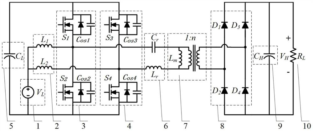
[0081] Aiming at the shortcomings of the existing isolated DC converter topology, such as narrow voltage control range and low efficiency, the present invention proposes a novel isolated DC boost converter based on a two-phase parallel boo...


PUM


Abstract

The invention belongs to the field of direct-current converters, particularly relates to an isolated direct-current boost converter of a two-phase parallel boost circuit and a control method of the isolated direct-current boost converter, and aims to solve the problem that an existing isolated direct-current converter cannot adapt to a wide voltage range and high gain and cannot realize high-efficiency conversion in a whole load range. According to the invention, a two-phase input inductor and two bridge arms of a full-bridge unit form a two-phase parallel Boost circuit for boosting and stabilizing an input DC voltage; the DC bus capacitor carries out voltage filtering after voltage boosting and voltage stabilization; the series resonance circuit resonates and realizes power transmission from the primary side to the secondary side through the high-frequency transformer; and the output rectifying and filtering circuit performs high-frequency rectifying and filtering on the output voltage of the high-frequency transformer to obtain output direct-current voltage. The high-frequency series resonance with the leakage inductance is introduced to eliminate the voltage peak caused by the leakage inductance, the high-frequency resonance is combined with the PWM modulation to realize the soft switching of the switching tube in a wide voltage range, and the loss is reduced while the gain and the efficiency are improved.

Description

technical field [0001] The invention belongs to the field of DC converters, and particularly relates to an isolated DC boost converter with a two-phase parallel boost circuit and a control method thereof. Background technique [0002] DC boost converters have broad application prospects in photovoltaic, wind power and other renewable energy power generation and electric vehicles and other systems. In applications with higher voltage and higher power, considering the safety of the system, the converter is generally required to have an isolation function. And because photovoltaics, wind power, fuel cells, etc. have the characteristics of wide-ranging output voltage fluctuations, DC converters are required to achieve maximum power tracking (MPPT) and output voltage regulation functions within a wide input voltage range. [0003] At present, the commonly used isolated DC boost converters based on two-phase parallel boost circuits mainly adopt push-pull topology, phase-shift ful...

Claims


Application Information

Patent Timeline
Patent Type & Authority Applications(China)
IPC IPC(8): H02M3/335H02M1/00H02M1/32
CPCH02M3/3353H02M1/00H02M1/32Y02T10/7072
Inventor 曹国恩王一波王环
Owner INST OF ELECTRICAL ENG CHINESE ACAD OF SCI
Why Eureka
Try Eureka