
Camera with automatic rotating device

An automatic rotation and camera technology, applied in the field of cameras, can solve problems such as follow-up shooting, blind spots, and poor pertinence of surveillance video, and achieve the effects of avoiding waste and saving energy consumption

Inactive Publication Date: 2017-02-22
CHENGDU HANZHI INFORMATION TECH
View PDF0 Cites 4 Cited by
  • Summary
  • Abstract
  • Description
  • Claims
  • Application Information

AI Technical Summary

Problems solved by technology

[0004] The purpose of the present invention is to provide a camera with an automatic rotating device, which is used to solve the problem of being easily stuck by the rotation of the remote sensing ball head in the prior art, and there is a blind area. The present invention sets a fixed inner ring and a rotating outer ring And through the reversing motor drive, the camera can be rotated 360 degrees to achieve no dead angle monitoring
The camera can only capture a single video image in a specific area, and cannot automatically follow and shoot with the sounding and luminous objects, and cannot accurately capture the images of moving objects; second, the existing cameras need to rely on the background control of the monitoring system. The boot recording will continuously record the video images in a specific area, resulting in the surveillance video not being highly targeted, and consuming a lot of energy and storage equipment.

Method used


Image

  • Camera with automatic rotating device
  • Camera with automatic rotating device
  • Camera with automatic rotating device

Examples


Embodiment 1

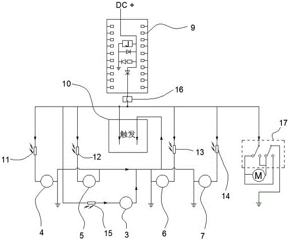
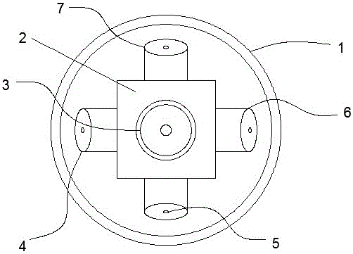
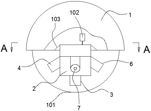
[0027] combined with Figure 1-6 As shown in the structure and circuit connection mode, a camera with an automatic rotation device includes a housing 1, a camera body installed in the housing 1 and a controller 9 for controlling the opening and closing of the camera body, so The camera body is connected with the housing 1 through a rotating device that can automatically rotate, and the automatic rotating device is composed of a fixed boss 103 connected with the housing 1, a fixed outer ring 104 connected with the fixed boss 103, and a fixed outer ring 104 that is slidably embedded in the fixed body. The rotating inner ring 105 inside the outer ring 104 is provided with gear teeth on the inner circumference of the rotating inner ring 105 and meshes with the driving gear 106 for driving the rotating inner ring 105 forward and backward, and the driving gear 106 is driven by the reversing motor 102 ; The housing 1 also includes a controller 9 for controlling the forward and revers...


PUM


Abstract

The invention discloses a camera with an automatic rotating device. The camera comprises a shell and a controller installed in the shell, a mounting hole used for accommodating circuits and mounting and fixing the camera is formed in the top of the shell in a penetration manner, the controller is connected with the camera by a voice operated switch, a mounting seat for mounting the camera is connected to the lower part of the shell, the camera is characterized in that the mounting seat is of a rectangular structure, a first lens is installed on a lower surface of the mounting seat, and a second camera, a third camera, a fourth camera and a fifth camera are separately installed on four side faces of the mounting seat. According to the camera disclosed by the invention, the camera aligned to a bright site can be automatically opened by a light resistor connected with the camera in series to perform camera shooting, and after the visible light disappears, the automatic switchover acousto-optic control camera can be automatically closed, thereby not only saving the energy consumption, avoiding 24-hour recording and avoiding the waste problem of storage device, but also accurately performing tracking shooting on a luminous moving object and retaining useful segments.

Description

technical field [0001] The invention relates to the field of cameras, in particular to a camera with an automatic rotating device. Background technique [0002] The camera is one of the most commonly used and frequently used products in the current surveillance camera field. It has been widely promoted because of its high-definition video collection function and characteristics, which can be collected and stored, and the facts can be reproduced. [0003] Existing monitoring cameras are usually controlled by the same background system. A single camera can only shoot a designated area, which is prone to large blind spots; It can be solved by cross-installation, and some can be solved by technological innovation, such as further developing a camera that can adjust the angle and perform a certain range of swing and rotation on the basis of a single camera, so that a camera can be changed by changing According to the position and orientation of the camera, more pictures can be c...

Claims


Application Information

Patent Timeline
IPC IPC(8): H04N5/232H04N5/247H04N7/18
CPCH04N7/181H04N23/60H04N23/90
Inventor 肖黎
Owner CHENGDU HANZHI INFORMATION TECH
Learn More