

Sleep regulation system
A control system and sleep technology, applied in the field of sleep control systems, can solve problems such as sleep insufficiency and sleep inertia reduction
- Summary
- Abstract
- Description
- Claims
- Application Information
AI Technical Summary
Problems solved by technology
Method used
Image

Examples
Embodiment approach 1
[0037] The sleep control system 1 according to Embodiment 1 will be described below with reference to the drawings.
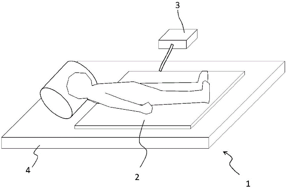
[0038] figure 1 It is a schematic perspective view of the sleep control system 1 used in this embodiment. The sleep control system 1 of the present embodiment includes a heating unit 2 for heating a human body, and a control unit 3 for controlling the heating operation of the heating unit 2 .
[0039] The warming unit 2 is provided above the mattress 4 and below the human body. Then, the warming part 2 generates heat using a nichrome wire, and contacts the human body to apply heat. In addition, in the present embodiment, the warming unit 2 is formed in such a size as to heat the range from the shoulders to the feet of the human body.
[0040] As a method of applying heat to the human body, there is also a method of raising the temperature itself, such as an air conditioner. However, people will feel uncomfortable when the temperature rises during sleep, wh...
Embodiment approach 2
[0069] A sleep control system 1a according to Embodiment 2 will be described below with reference to the drawings. This embodiment differs from Embodiment 1 in that a vibration sensor 10 is provided in the sleep control system 1a. In this embodiment, the description will focus on the differences from Embodiment 1. FIG.
[0070] Figure 6 It is a schematic perspective view of the sleep control system 1a used in this embodiment. Figure 7 It is a block diagram showing the structure of the control part 3a used in this embodiment. Figure 8 It is a flowchart for explaining the operation of the sleep control system 1a used in this embodiment.
[0071] Such as Figure 6 As shown, the sleep control system 1a of this embodiment is provided with a vibration sensor 10 in the warming part 2a. As the vibration sensor 10, a sensor using a piezoelectric element, an ultrasonic Doppler sensor, or the like may be used. Vibrations such as turning over of the human body are detected by the...
Embodiment approach 3
[0082] A sleep control system 1b according to Embodiment 3 will be described below with reference to the drawings. This embodiment differs from Embodiment 1 in that a sounder 11 is provided in the sleep control system 1b. In this embodiment, the description will focus on the differences from Embodiment 1. FIG.
[0083] Figure 9 It is a block diagram showing the structure of the control part 3b used in this embodiment. Figure 10 It is a flowchart for explaining the operation of the sleep control system 1b used in this embodiment.
[0084] Such as Figure 9 As shown, the sleep control system 1b of this embodiment includes a sounder 11 in the control unit 3b. Then, the control circuit 5b in the control unit 3b generates a signal at the scheduled wake-up time, and the sound as an alarm at the scheduled wake-up time flows out from the sounder 11 based on the signal.
[0085] Such as Figure 10 As shown, in the sleep control system 1b of this embodiment, after the control circ...
PUM
 Abstract
Description
Claims
Application Information