Stretcher

A technology of stretchers and loading parts, which is applied in the direction of stretchers, pressure vessels, ship construction details, etc.

Active Publication Date: 2017-02-22
FUJIDENORO +1
View PDF9 Cites 3 Cited by
  • Summary
  • Abstract
  • Description
  • Claims
  • Application Information

AI Technical Summary

Problems solved by technology

Such a problem is a problem newly discovered during the inventor's intention to develop a convenient and easy-to-use stretcher and continued intensive research

Method used


Image

  • Stretcher
  • Stretcher
  • Stretcher

Examples


Embodiment 1

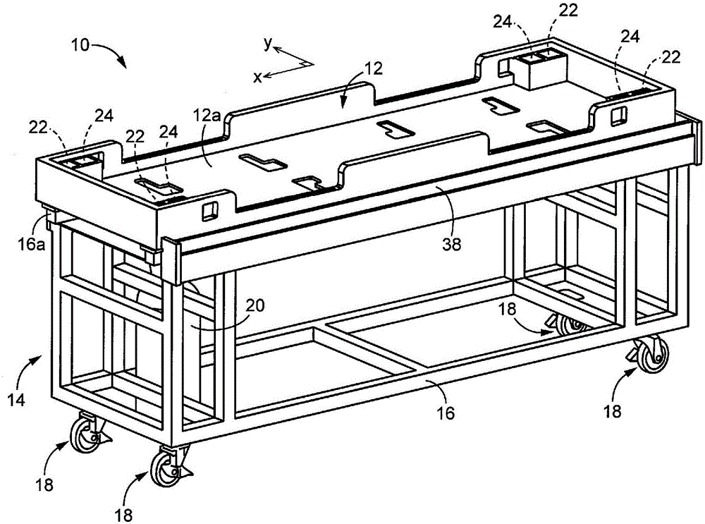
[0036] figure 1 It is a perspective view explaining an example of the structure of the stretcher 10 which is a preferable Example of this invention. The stretcher 10 includes, for example, a subject placement unit 12 on which a subject not shown is placed, and a transport device 14 that transports the subject placement unit 12 . The conveying device 14 includes, for example: a frame 16 made of a non-magnetic material such as aluminum alloy and a plurality of (in the figure 1 Among them are four) casters 18. In this embodiment, the non-magnetic material refers to a metal material such as aluminum alloy, titanium alloy, copper alloy, etc. that can ignore the influence of a magnetic field, a synthetic resin material, or a wooden material.

[0037] The caster 18 is, for example, a caster with a wheel diameter of φ100 mm or more, and the axle of the caster is a known caster device that can freely rotate 360° in a plane parallel to the ground (the ground on which the conveying dev...

Embodiment 2

[0058] Image 6 It is a perspective view explaining an example of the structure of the stretcher 100 which is another preferable Example of this invention. This stretcher 100 has a plurality of examinee placing parts 12 (in Image 6 Four in the middle) wheel unit 102 as the replacement of the wheel units 22,24. For example, one wheel unit 102 is provided at each of the four corners of the examinee placing unit 12 . All the components of the wheel unit 102 are preferably made of synthetic resin materials.

[0059] Figure 7 In the stretcher 100 of the present embodiment, in order to describe the structure of the wheel unit 102 included in the subject placing part 12, the stretching along the short side direction ( Figure 9 ~ Figure 11 A schematic side view of the examinee's placing part 12 is observed in the y-axis direction shown). Such as Figure 7 As shown, the wheel unit 102 includes: a wheel 104 whose axis is oriented so as to roll in the longitudinal direction of t...

Embodiment 3

[0067] Figure 12 with Figure 13 It is a perspective view explaining an example of the structure of the stretcher 150 which is still another preferable embodiment of this invention. In the description of this example used the Figure 12 to Figure 15 In the figure, for the sake of convenience, a state in which the subject placement unit 12 is not placed on the upper portion (installation platform 16 a ) of the transfer device 14 is shown in the figure. Such as Figure 12 with Figure 13 As shown, the conveying device 14 in the stretcher 150 of this embodiment includes a braking device 152 . The brake device 152 includes: a contact portion 154 that contacts (presses) the ground 158 on which the conveying device 14 is located; and an actuator 156 that switches the contact portion 154 by supplied air pressure. connected to the first state of the ground 158 (with Figure 12 Corresponding) and the second state where the abutting portion 154 is separated from the ground 158 (w...


PUM


Abstract

Provided is a stretcher which allows a subject support section on a transport device to be easily moved therefrom. A subject support section (12) is provided with: a set of wheels (26) rolling in the long-side direction; a set of wheels (32) rolling in the short-side direction; and cylinders (28, 34) provided corresponding to the set of wheels (26) and the set of wheels (32), respectively, and serving as switching devices for switching between a first state in which at least a part of each of the wheels (26, 32) is caused to protrude from the bottom surface (12b) of the subject support section (12) and a second state in which said at least a part of each of the wheels (26, 32) is not caused to protrude from the bottom surface (12b). As a result of this configuration, the subject support section (12) can be easily moved relative to a transport device (14) in any of the long -side and short- side directions of the subject support section (12), and in addition, due to a relatively simple structure, sufficient durability can be ensured even if a synthetic resin material is used for wheel units (22, 24).

Description

technical field [0001] The present invention relates to a stretcher for transporting a person to be examined when a nuclear magnetic resonance apparatus is used for examination or the like. Background technique [0002] There is known a stretcher including a subject placing unit on which a subject is placed, and a transport device for transporting the subject placing unit. In this stretcher, after the patient loading unit on which the patient is placed is transported by the transport device, the patient loading unit may be moved from the transport device to another place. A technique for simply performing such movement has been proposed. For example, the sliding mechanism of the mounting table in the stretcher etc. which are described in patent document 1 is such an example. According to this technique, after the loading table is moved to the vicinity of the bed by the conveying device, the loading table can be easily moved to the center of the bed by the slide mechanism. ...

Claims


Application Information

Patent Timeline
Patent Type & Authority Applications(China)
IPC IPC(8): A61G1/02
CPCA61G1/0287A61G1/0212A61G2210/50A61G1/0293A61B6/0407A61G1/02A61G1/003F17C1/00F17C2205/0394
Inventor 有村健松山贡荻野尚菱川良夫宫崎秀树野间庆一樱木红莉
Owner FUJIDENORO
Why Eureka
Try Eureka