
Spinning machine having a false twist device

A technology of spinning machine and equipment, applied in the field of spinning machine with false twisting equipment, can solve the problems that are not proposed and difficult to adjust the correct speed of false twisting belt, etc.

Inactive Publication Date: 2017-02-22
MASCHINENFABRIK RIETER AG
View PDF6 Cites 4 Cited by
  • Summary
  • Abstract
  • Description
  • Claims
  • Application Information

AI Technical Summary

Problems solved by technology

The disadvantage of this prior art is that it is difficult to adjust the correct speed of the false twist belt and furthermore it has not been proposed for use in spinning machines

Method used


Image

  • Spinning machine having a false twist device
  • Spinning machine having a false twist device
  • Spinning machine having a false twist device

Examples


Embodiment Construction

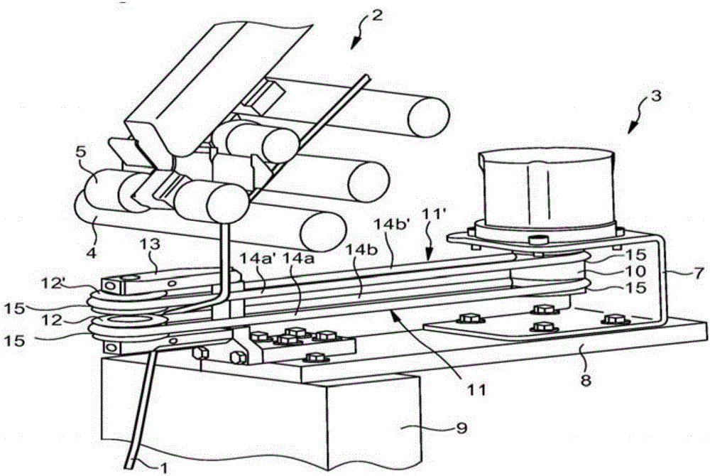
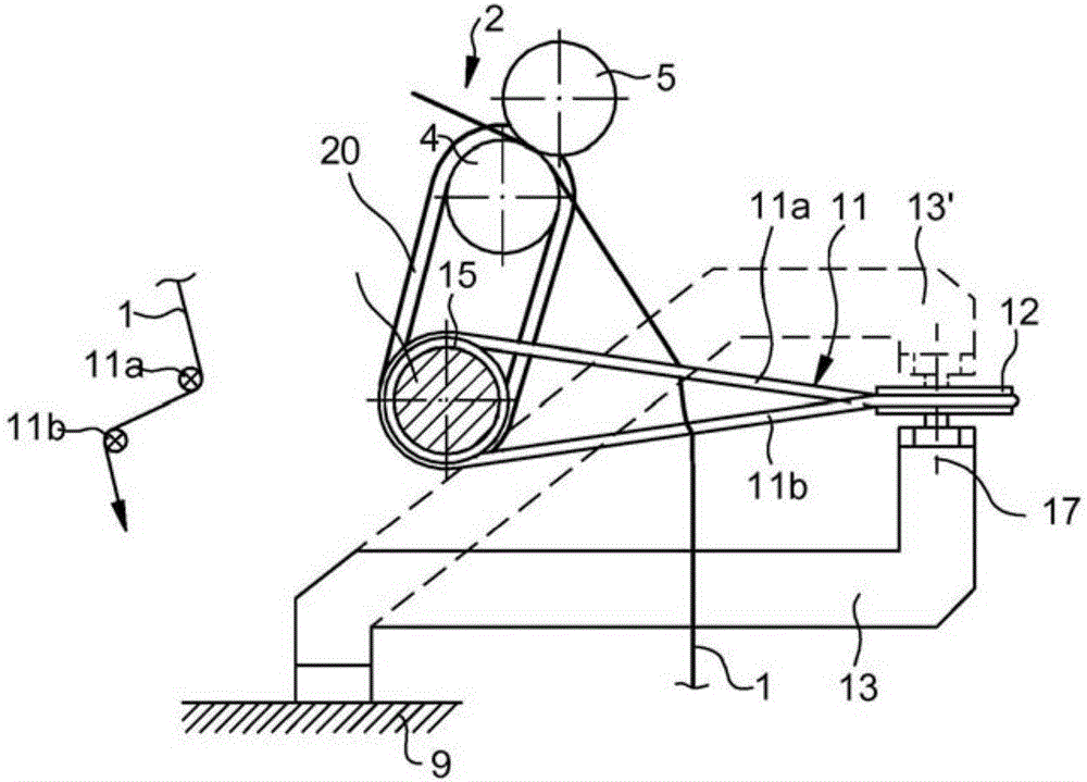
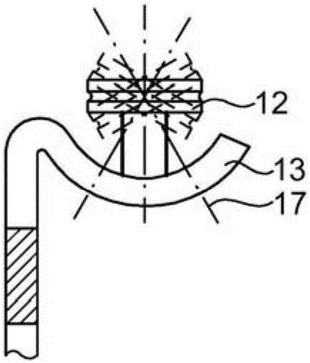
[0078] exist figure 1 shows a cutout of a spinning unit according to the invention in a perspective view. Here, the yarn 1 runs through a drafting device 2 and a false twisting device 3 . In conjunction with the false twisting device 3, the yarn 1 is wound onto bobbins on a spinning device not shown. The drafting device 2 is shown in excerpt. In addition to the different known upper and lower rollers and the pressing arms to which the upper rollers are fastened, in particular a delivery drum 4 and a delivery top roller 5 at the end of the drafting device 2 are shown. A false twisting device 3 is arranged below the drafting device 2 . The false twisting device 3 has a single drive 6 which is fixed on a motor console 7 . The motor console is in turn connected to the frame 9 via a board 8 . The unit drive 6 drives the two belts 11 and 11' via the drive disc 10. Each of the belts 11 and 11' is diverted by front rollers 12 and 12'. Front rollers 12 and 12' are secured at...


PUM


Abstract

The invention relates to a spinning machine having a false twist device, in particular a ring spinning machine having a plurality of spinning units arranged adjacent to each other, wherein each spinning unit has a drawing frame (2) having an output cylinder (4) for drawing a sliver, a spinning device for twisting the drawn sliver into a thread (1), and a false twist device (3) arranged between the drawing frame (2) and the spinning device. The false twist device (3) has at least one belt (11) driven by means of a driving device, wherein the thread (1) wraps in a Z or S shape around two belt runs (14a, 14b) which move in opposite directions and extend substantially perpendicularly to the thread (1). The main direction of the belt runs (14a, 14b) extends substantially perpendicular to the axis of the output cylinder (4) in particular in the region of the thread wrapping.

Description

technical field [0001] The invention relates to a spinning machine, in particular a ring spinning machine, with a plurality of spinning units arranged next to each other, wherein each spinning unit has a drafting device with a delivery drum for drafting a fiber bundle , a spinning device for twisting a drawn fiber bundle into a yarn, and a false twisting device arranged between the drafting device and the spinning device, wherein the false twisting device has: at least one A belt and two opposite belt returns, which extend substantially transversely to the yarn and are wound around the yarn in a Z-shape or S-shape; and a corresponding false twisting device. Background technique [0002] A spinning machine is known from WO 2010 / 015185 A1 in which a false twisting device is arranged between a drafting device which drafts the fiber bundle and a bobbin which winds the fiber bundle. According to one embodiment disclosed there, the false twist device consists of a single belt whi...

Claims


Application Information

Patent Timeline
IPC IPC(8): D02G1/08D01H1/02D01H1/241
CPCD01H7/923D02G1/08D01H1/02D01H1/241
Inventor G·斯塔莱克
Owner MASCHINENFABRIK RIETER AG
Learn More