Lace fabric and method of attaching lace fabric to an adherend

A technology of adherend and lace, applied in the direction of fabric, knitting, loom, etc., can solve the problems of uneconomical, inconvenient cutting pattern, inability to separate adhesive film, etc., and achieve the effect of easy to complete the manufacture and easy to use.

Active Publication Date: 2019-03-15
赵景惠
View PDF13 Cites 0 Cited by
  • Summary
  • Abstract
  • Description
  • Claims
  • Application Information

AI Technical Summary

Problems solved by technology

However, this traditional technique cannot be applied to lace fabrics
The reasons are, firstly, that it is neither convenient nor economical to adjust the cutting pattern of a single-edged knife in the manufacturing unit due to the extreme variability in the design of lace fabrics
In addition, since the lace fabric includes weaving roughness and contains many holes, it cannot be sufficiently laminated with the adhesive film, it is difficult to be attached to an adherend
Even if the adhesive film is attached to the lace fabric, the user is still subject to the critical limitation of not being able to detach the adhesive film from the lace fabric due to the presence of said many holes

Method used


Image

  • Lace fabric and method of attaching lace fabric to an adherend
  • Lace fabric and method of attaching lace fabric to an adherend
  • Lace fabric and method of attaching lace fabric to an adherend

Examples


example 1

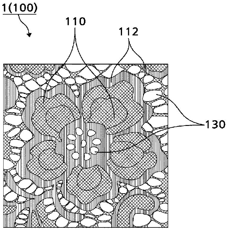
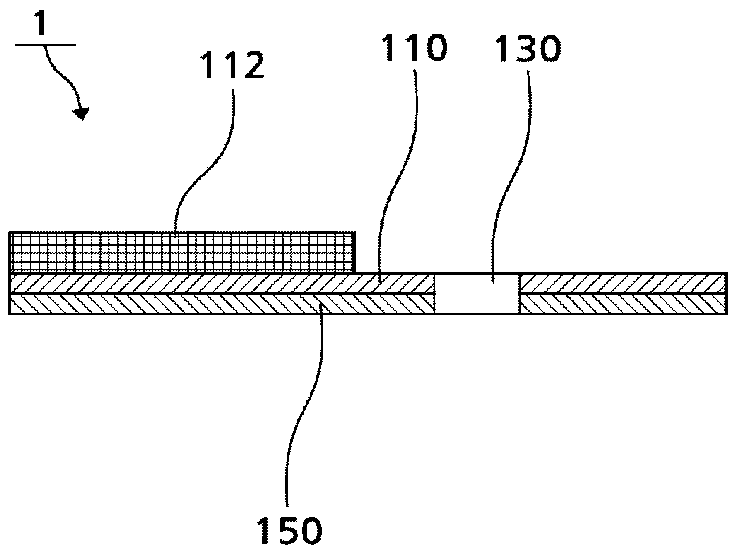
[0038] figure 1An exemplary surface 100 configuration of the lace fabric 1 of the present invention is schematically illustrated. The surface 100 of the lace fabric 1 comprises: a bottom thread layer 110, which is a coverage area (coverage factor) in which the threads of the knitted structure form a surface; and an open area (opening factor) 130, in which no said Knit construction. A lace design pattern is formed on the bottom thread layer 110, and the lace design pattern is provided in a plurality of layers according to the design. In order to express both the density of the knitted structure and the thickness of the threads, as well as the lace pattern and texture, the plurality of layers may include a pattern layer 112 configured to be represented by re-weaving on the surface of the bottom thread layer 110 Floral silk pattern. In other words, the lace design pattern is formed by weaving the pattern layer 112 on the bottom thread layer 110 . According to the pattern laye...

example 2

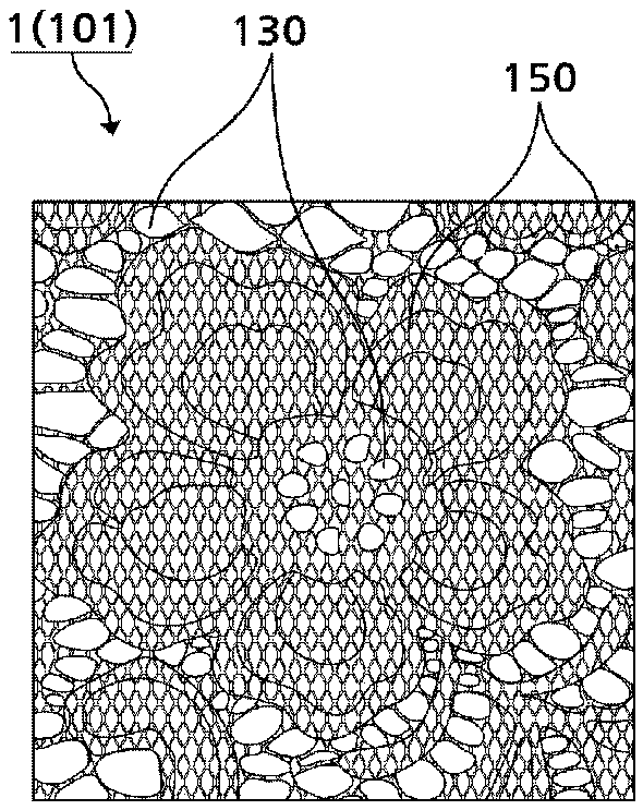
[0054] In the above example 1, the hot-melt coating layer 150 is formed on the rear surface of the lace fabric 1, but the following preferred example 2 of the present invention can be different from the example 1 in the following way: the hot-melt coating is performed on the thread itself of the lace fabric . Other configurations are essentially the same.

[0055] Such as Figure 5A to Figure 5C Shown in, lace fabric of the present invention is to be woven by two kinds of different silk threads. Furthermore, the lace fabric is formed by two different weaving layers. as in Figure 5A Among them, the bottom thread 11 includes a core body 11a and a coating layer 11b. A yarn can be generally used as the core 11a. In the present invention, the hot-melt coating layer 11b is formed on the entire surface of the core body 11a of the bottom wire 11 . Instead, as in Figure 5B As shown in , unlike the bottom thread 11, the surface of the effect thread 12 does not include said hot-...


PUM


Abstract

The invention relates to a lace fabric and a method for attaching the lace fabric to an adherend. The lace fabric (1) of the present invention is a lace fabric woven from two different types of threads, wherein the through-hole area and the cover factor area are formed by weaving the bottom yarn; The surface of the bottom yarn layer is formed by weaving pattern threads; and the surface of the core of the bottom yarn is hot-melt coated, while the pattern thread is not hot-melt coated. Since no adhesive film is used at all, not only is manufacturing easy to accomplish, but it is also extremely easy to use. Attachment of the lace fabric is easily achieved by merely placing the lace fabric on the adherend followed by ironing.

Description

technical field [0001] The present invention relates to a lace fabric. Background technique [0002] Lace fabrics are widely used as decorations in industries such as clothing or stuffed toys. Lace fabric is shipped as a stand-alone accessory material, or attached to clothing or stuffed toys. Regardless of the distribution channel, lace fabrics often end up being used by being attached to an adherend, which is the substrate. However, there have been many difficulties and technical limitations in conventional techniques related to attaching lace fabrics to adherends. [0003] Unlike other fabrics, lace fabrics are usually produced by knitting using a warp knitting machine. Since there are many portions with pores throughout the surface area of ​​the fabric, the area occupied by the attachment surface is extremely small. Mesh structures can be found in various fabrics. Representative examples include non-woven fabrics in which fibers are intertwined to form a flat surface...

Claims


Application Information

Patent Timeline
Patent Type & Authority Patents(China)
IPC IPC(8): D04B21/06D03D15/00
CPCD03D15/00D03D31/00
Inventor 赵景惠
Owner 赵景惠
Why Eureka
Try Eureka