Gearbox of aircraft turbine engine

一种涡轮发动机、齿轮箱的技术,应用在机器/发动机、发动机的润滑、发动机元件等方向,达到优化体积的效果

Active Publication Date: 2017-02-22
SAFRAN AIRCRAFT ENGINES SAS
View PDF8 Cites 8 Cited by
  • Summary
  • Abstract
  • Description
  • Claims
  • Application Information

AI Technical Summary

Problems solved by technology

This technique has disadvantages related to the fact that the annular oil reservoir supplying lubricating oil to the splines only fills when the engine is stopped

Method used


Image

  • Gearbox of aircraft turbine engine
  • Gearbox of aircraft turbine engine
  • Gearbox of aircraft turbine engine

Examples


Embodiment Construction

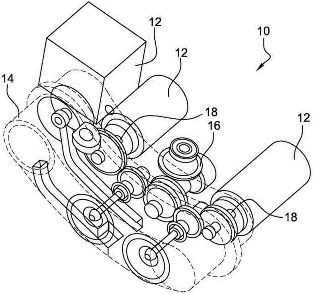
[0021] first refer to figure 1 , which shows an accessory gearbox 10 for driving a device 12 of a turbine engine, such as an aircraft turbojet or turboprop. Such an accessory gearbox is described in detail in document FR-A1-2 941744.

[0022] The gearbox 10 is used to collect the mechanical power from the turbine engine and transmit the mechanical power to various pieces of equipment, such as pumps, generators and the like. Transmission is accomplished through a kinematic chain of rotating elements that mesh with each other to form a gear train or accessory train.

[0023] The accessory gearbox 10 comprises a case 14 defining housings for rotating elements, such as pinions and rolling bearings, for example. The kinematic chain is connected to the drive shaft 16, either radial or intermediate of the turbine engine, and to the kinematic shaft 18 of the pieces of equipment. The accessory gearbox 10 is fastened to the turbine engine, and pieces of equipment are typically in tur...


PUM


Abstract

The invention relates to a gearbox (10) of an aircraft turbine engine, which includes a casing (14) defining an enclosure for housing oil-lubricated rotary elements, and at least one tubular sleeve (30) coupled to the rotary elements and configured such as to rotate a shaft (18), said sleeve comprising splines (26) configured to engage with complementary splines (24) of said shaft, characterised by also including means (42, 44) for recovering lubrication oil from the rotary elements and for conveying the recovered oil by trickling towards the splines in order to lubricate same.

Description

technical field [0001] The invention relates to a gearbox for an aircraft turbine engine. Background technique [0002] The prior art includes in particular documents EP-A1-2 711 505, US-A-3,621,937 and GB-A-2 488 142. [0003] A gearbox for an aircraft turbine engine, in particular an aircraft or helicopter turbojet or turboprop, may consist of an accessory gearbox (AGB, Accessory Gear Box) which is used to drive the turbine engine Equipment such as pumps, generators, etc. The accessory gearbox transmits the mechanical power from the turbine engine to the equipment through a kinematic chain consisting of rotating elements such as pinions or rolling bearings. A gearbox for an aircraft turbine engine may also consist of a transfer gear box (TGB, Transfer Gear Box), for example to kinematically connect the accessory gearbox to the turbine shaft of the turbine engine by using two transmission shafts, which Optionally angled and connected to each other through a transmission ...

Claims


Application Information

Patent Timeline
Patent Type & Authority Applications(China)
IPC IPC(8): F02C7/06F02C7/32F01D25/18F16H57/04
CPCF01D25/18F02C7/06F02C7/32F16H57/0431F16H57/0495F05D2260/4031F05D2240/63F01D15/08F01D15/10F01D15/12F01D25/16F05D2220/323F05D2260/98
Inventor 让-巴普蒂斯特·艾蒂安·伯纳德·勒普里特尔
Owner SAFRAN AIRCRAFT ENGINES SAS
Why Eureka
Try Eureka