Test tube

A test tube and tube diameter technology, applied in the field of liquid storage, can solve the problems of leak-proof, convenient connection, tilt, liquid spilling and other problems that are difficult to reflect the function, and achieve the effect of reducing the amount of body fluid collected, reducing the cost of use, and easily perfusing liquid

Inactive Publication Date: 2017-03-01
WUXI KAISHUN MEDICAL DEVICE MFG CO LTD
View PDF6 Cites 1 Cited by
  • Summary
  • Abstract
  • Description
  • Claims
  • Application Information

AI Technical Summary

Problems solved by technology

[0007] like image 3 As shown, if the outer diameter d1 of the test tube is reduced while the inner diameter D3 of the test tube is reduced, that is, D3 is smaller than D5, and d1 is smaller than d, although the problem of material consumption and cost is solved, the test tube 100 cannot be placed upright on the test tube rack shaking on the test tube rack, causing the test tube placed on the test tube rack to tilt, and even causing the liquid in the test tube to spill
On the other hand, due to the reduced diameter of the opening of the test tube, it is difficult for the opening of the test tube to cooperate with other parts, such as test tube stoppers, connectors, etc., which make it difficult and inconvenient to perfuse liquid, and it is also difficult to reflect other related functions such as leak prevention and convenience. Connections, etc. Furthermore, test tubes with reduced outer diameters cannot be used normally on testing instruments (general testing equipment cannot clamp test tubes with reduced outer diameters, and the inner diameters of testing equipment test tube racks where test tubes are placed are similar and relatively large. If the outer diameter of the test tube is small, it will shake when placed inside), it is not convenient to use the instrument to directly detect the liquid in the test tube

Method used


Image

  • Test tube
  • Test tube
  • Test tube

Examples


Embodiment 1

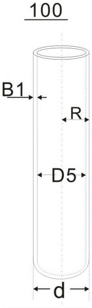
[0056] Example 1: Attached below figure 1 , Figure 4 , Figure 5 , Figure 6 , Figure 7 The present invention is further described.

[0057] A test tube 100 includes an annular side wall 31 and a bottom sealing plate 32 . The liquid storage portion 24 is enclosed by the annular side wall 31 and the bottom sealing plate 32 .

[0058] The test tube 100 includes a test tube upper part 21 , a test tube middle part 22 and a test tube lower part 23 . The upper part 21 of the test tube is provided with an opening 33 , and the opening 33 communicates with the liquid storage part 24 . The upper part 21 of the test tube is used for connecting with a liquid taking device, so that the liquid flows into the liquid storage part 24 through the opening 33 . The middle part 22 of the test tube and the lower part 23 of the test tube are used for storing liquid.

[0059] The inner diameter of the reservoir 24 is D. The inner diameter D of the liquid storage part 24 is smaller than t...

Embodiment 2

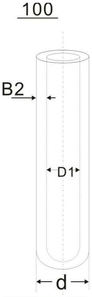
[0069] Example 2: Attached below figure 1 , Figure 9 , Figure 10 , Figure 13 The present invention is further described.

[0070] A test tube 100 includes an annular side wall 31 and a bottom sealing plate 32 . The liquid storage portion 24 is enclosed by the annular side wall 31 and the bottom sealing plate 32 .

[0071] The test tube 100 includes a test tube upper part 21 , a test tube middle part 22 and a test tube lower part 23 . The upper part 21 of the test tube is provided with an opening 33 , and the opening 33 communicates with the liquid storage part 24 . The upper part 21 of the test tube is used for connecting with a liquid taking device, so that the liquid flows into the liquid storage part 24 through the opening 33 . The middle part 22 of the test tube and the lower part 23 of the test tube are used for storing liquid.

[0072] A bend 34 is provided at the connection between the upper part 21 of the test tube and the middle part 22 of the test tube, a...

Embodiment 3

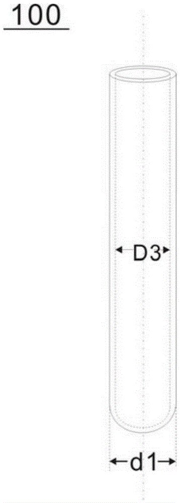
[0078] Example 3: Attached below figure 1 , Figure 15 , Figure 16 The present invention is further described.

[0079] A test tube 100 includes an annular side wall 31 and a bottom sealing plate 32 . The liquid storage portion 24 is enclosed by the annular side wall 31 and the bottom sealing plate 32 .

[0080] The test tube 100 includes a test tube upper part 21 , a test tube middle part 22 and a test tube lower part 23 . The upper part 21 of the test tube is provided with an opening 33 , and the opening 33 communicates with the liquid storage part 24 . The upper part 21 of the test tube is used for connecting with a liquid taking device, so that the liquid flows into the liquid storage part 24 through the opening 33 . The middle part 22 of the test tube and the lower part 23 of the test tube are used for storing liquid.

[0081] The inner diameter of the test tube upper part 21 and the test tube middle part 22 is D5, which is consistent with the test tube inner dia...


PUM


Abstract

The invention relates to the field of medical appliances, and especially relates to a test tube used for storing liquid, such as body fluids or blood. The test tube includes an annular side wall and a bottom sealing board, an opening is formed on the upper part of the test tube. The upper part of the test tube is matched with and connected to other equipment. The middle and lower parts of the test tube are used for storing the liquid. A bended part is formed between the upper and the lower parts of the test tubes, wherein the diameter of the upper part is larger than that of the lower part, so that liquid storage quantity of the liquid storage part can be reduced when liquid at the same liquid level is collected. The test tube is reduced in volume and reduces use amount of raw materials, greatly reduces cost and is convenient to fill with the liquid. In addition, when the test tube is fixed with a test tube bracket or a detection device, the test tube is not liable to shake.

Description

technical field [0001] The invention relates to the field of medical equipment, in particular to a test tube for storing liquid, such as body fluid or blood. Background technique [0002] In the prior art, most of the collection and storage devices for body fluids are test tubes. When detecting body fluid, the body fluid in the test tube must reach a certain volume to achieve the purpose of detection. For example, when using a test strip for detection, the test strip must reach a certain depth when it is placed in the test tube so that all the test parts of the test strip can be immersed in the liquid, that is, the liquid in the test tube must have a higher liquid level (closer to the mouth of the tube) in order to use it. The liquid is in contact with all the detection parts of the test strip, so only when the liquid level of the liquid in the test tube is close to the mouth of the tube is it convenient for the dropper to draw liquid and detect the test strip. When collec...

Claims


Application Information

Patent Timeline
Patent Type & Authority Applications(China)
IPC IPC(8): B01L3/14
Inventor 不公告发明人
Owner WUXI KAISHUN MEDICAL DEVICE MFG CO LTD
Why Eureka
Try Eureka