Pump bearing structure

A technology for bearings and pumps, applied to bearing components, shafts, bearings, pumps, etc., can solve the problems of increased maintenance costs, increased wear and water leakage opportunities, and reduced tightness of the adapter 74, so as to improve wear and water leakage, The effect of streamlining widget settings

Inactive Publication Date: 2017-03-01
DENGYUAN WATER TREATMENT MACHINERY TAICANG CO LTD
View PDF9 Cites 0 Cited by
  • Summary
  • Abstract
  • Description
  • Claims
  • Application Information

AI Technical Summary

Problems solved by technology

[0003] The above-mentioned adapter 74 is usually made of plastic. Under the high-speed rotation of the rotating shaft 71, the adapter 74 is easily worn and the closeness between it and the rotating shaft 71 is reduced, and it is difficult to accurately transmit the rotation of the rotating shaft 71 and affect the pressurization pump. effectiveness
What's more, the installation of the adapter 74 will cause an increase in the number of components, so the wear and tear between the components and the chance of water leakage will also be aggravated, so as to increase the maintenance cost, which really needs to be improved.

Method used


Image

  • Pump bearing structure
  • Pump bearing structure
  • Pump bearing structure

Examples


Embodiment Construction

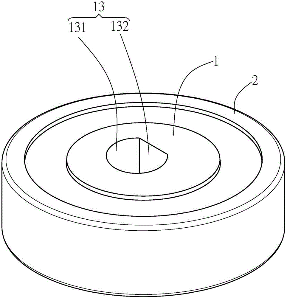
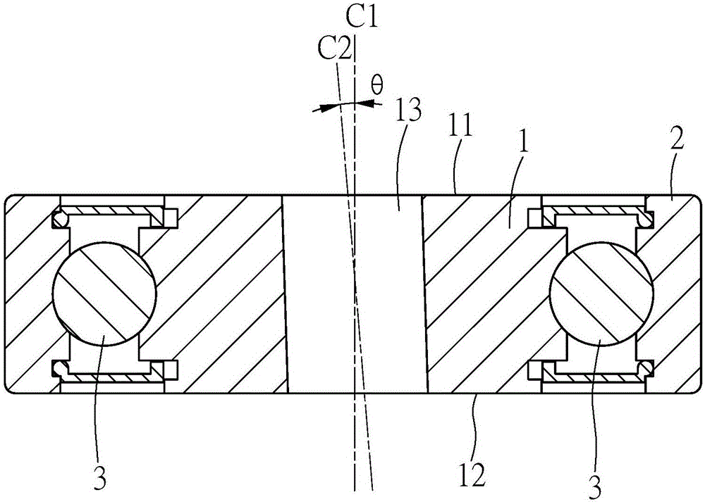
[0023] see figure 1 , 2 , shows the first embodiment of the pump bearing structure provided by the present invention, which includes an inner shaft sleeve 1 and an outer shaft sleeve 2, wherein the outer shaft sleeve 2 is arranged on the outer periphery of the inner shaft sleeve 1, and can be relatively The inner shaft sleeve 1 rotates. Several rolling elements 3 are arranged between the outer bushing 2 and the inner bushing 1 to reduce the friction between the outer bushing 2 and the inner bushing 1 and facilitate the relative rotation between the two.

[0024] The inner sleeve 1 has a first top surface 11 and a first bottom surface 12. In this embodiment, the first top surface 11 and the first bottom surface 12 are parallel to each other, and the center of the inner sleeve 1 defines an axis C1, The axis C1 is perpendicular to the top surface 11 and the bottom surface 12 at the same time.

[0025] On the other hand, a first slanted hole 13 is integrally provided in the in...


PUM


Abstract

The invention provides a pump bearing structure. The pump bearing structure comprises an inner shaft sleeve and an outer shaft sleeve, wherein the inner shaft sleeve has a first top surface and a first bottom surface; the first top surface is parallel to the first bottom surface; an axial direction is defined in the center of the inner shaft sleeve; the inner shaft sleeve is integrally provided with a first inclined through hole for penetrating from the first top surface to the first bottom surface, wherein the extending direction of the first inclined through hole is relatively inclined to the axial direction of the inner shaft sleeve to define an inclined angle; the outer shaft sleeve is arranged at the outer periphery of the inner shaft sleeve, and can rotate corresponding to the inner shaft sleeve; and multiple rolling pieces are arranged between the outer shaft sleeve and the inner shaft sleeve. The pump bearing structure can simplify the component setting of an adapter, and meanwhile, improves the wear and water leakage conditions among components after reducing the components.

Description

technical field [0001] The invention relates to a pump bearing structure, especially a pressurized pump bearing. Background technique [0002] The structure of the known booster pump is as Figure 8 As shown, the top piece 73 arranged on a driving rod 72 by being inclined relative to the rotating shaft 71 of a motor produces a reciprocating axial displacement when being driven by the rotating shaft 71 to convect the water flowing through the pump. Pressurization. In order to make the driving rod 72 or the top piece 73 form an oblique setting relative to the rotating shaft 71, the rotating shaft 71 needs to be sleeved with an adapter 74 first, and the adapter 74 is then connected to a bearing 75, and the bearing 75 is then connected to each drive rod 72 . Wherein the shaft hole 741 of the adapter 74 is a slanted hole deviated from its axis, for it to be sleeved on the rotating shaft 71 to present an oblique shape, and then the bearing 75, the drive rod 72 and the top plate ...

Claims


Application Information

Patent Timeline
Patent Type & Authority Applications(China)
IPC IPC(8): F04D29/049F16C33/58
Inventor 邓忠荣
Owner DENGYUAN WATER TREATMENT MACHINERY TAICANG CO LTD
Why Eureka
Try Eureka