Auxiliary power supply circuit

An auxiliary power supply and circuit technology, applied in the direction of high-efficiency power electronic conversion, electrical components, and adjustment of electrical variables, can solve the problems of high cost, low conversion efficiency, and low power density, and achieve high conversion efficiency and power density, wide input Range, Guaranteed Conversion Efficiency and Effect of Power Density

Active Publication Date: 2017-03-01
EMERSON NETWORK POWER CO LTD
View PDF5 Cites 4 Cited by
  • Summary
  • Abstract
  • Description
  • Claims
  • Application Information

AI Technical Summary

Problems solved by technology

[0005] The technical problem to be solved by the present invention is to provide a method that can fundamentally i

Method used


Image

  • Auxiliary power supply circuit
  • Auxiliary power supply circuit
  • Auxiliary power supply circuit

Examples


Example Embodiment

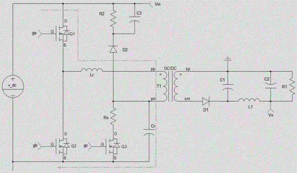
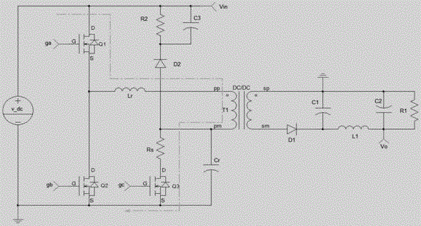
[0034] Such as figure 1 As shown, the auxiliary power supply circuit of the present invention includes a power conversion module 100 and a secondary output module 200. The power conversion module 100 is connected to the input voltage and transforms the input voltage. The secondary output module 200 receives the converted voltage from the power conversion module 100 and outputs it. In the present invention, the power conversion module 100 switches between a flyback mode and an LLC mode based on the input voltage. When the input voltage is lower than or equal to the set value (for example, 0-300V), the power conversion module 100 switches to the flyback mode. At this time, the entire auxiliary power supply circuit can work in the hard-switching state in the flyback mode. Thereby ensuring a wide input range. When the input voltage is higher than the set value (for example, 300-400V), the power conversion module 100 switches to LLC mode. At this time, the entire auxiliary power c...


PUM


Abstract

The invention relates to an auxiliary power supply circuit. The auxiliary power supply circuit comprises a power transformation module and a secondary output module. The power transformation module is used for receiving input voltage and transforming the input voltage. The secondary output module is sued for outputting transformed voltage. The power transformation module switches between a flyback mode and an LLC mode based on the input voltage. In this way, because the power transformation module switches between the flyback mode and the LLC mode based on the input voltage, the auxiliary power supply circuit can work in a hard switching state in the flyback mode, thereby ensuring a wide input range, and can work in a soft switching state in the LLC mode, thereby ensuring high transformation efficiency and power density.

Description

technical field [0001] The present invention relates to the field of power supply, more specifically, to an auxiliary power supply circuit. Background technique [0002] The auxiliary power supply is a very basic and very important part of the electronic circuit. The auxiliary power supply circuit generally adopts a flyback conversion circuit. The flyback conversion circuit has the following obvious advantages: the circuit is simple and the input range is wide. But at the same time, the flyback circuit also has the following obvious disadvantages: the conversion efficiency is very low, generally only about 70%. Therefore, there is an urgent need for an auxiliary power supply circuit with high conversion efficiency. [0003] In view of the above problems, the solution adopted in the prior art is to use high-performance switching devices and high-performance magnetic devices in the circuit, and reduce the switching frequency at the same time, so as to reduce the loss in the...

Claims


Application Information

Patent Timeline
IPC IPC(8): H02M3/335H02M1/32
CPCY02B70/10
Inventor 吕华军朱建华
Owner EMERSON NETWORK POWER CO LTD
Why Eureka
Try Eureka