
Resonant power converter with half bridge and full bridge operations and method for control thereof

a technology of resonant power converter and half bridge, which is applied in the direction of electric variable regulation, process and machine control, instruments, etc., can solve the problems of narrow operation range of resonant power converter and inability to operate in a wide input voltage range, and achieve the effect of wide input rang

Active Publication Date: 2012-08-14
SEMICON COMPONENTS IND LLC
View PDF3 Cites 3 Cited by
  • Summary
  • Abstract
  • Description
  • Claims
  • Application Information

AI Technical Summary

Benefits of technology

[0006]The object of the present invention is to provide a control scheme to solve this problem. It allows the resonant power converter can be operated in wide input range. The present invention provides a resonant power converter with half bridge and full bridge operations and a method for control thereof.

Problems solved by technology

The drawback of the resonant power converter is its narrow operation range.
It cannot be operated in a wide input voltage range.

Method used


Image

  • Resonant power converter with half bridge and full bridge operations and method for control thereof
  • Resonant power converter with half bridge and full bridge operations and method for control thereof
  • Resonant power converter with half bridge and full bridge operations and method for control thereof

Examples


Embodiment Construction

[0021]Reference will now be made in detail to the present embodiments of the invention, examples of which are illustrated in the accompanying drawings. Wherever possible, the same reference numbers are used in the drawings and the description to refer to the same or like parts.

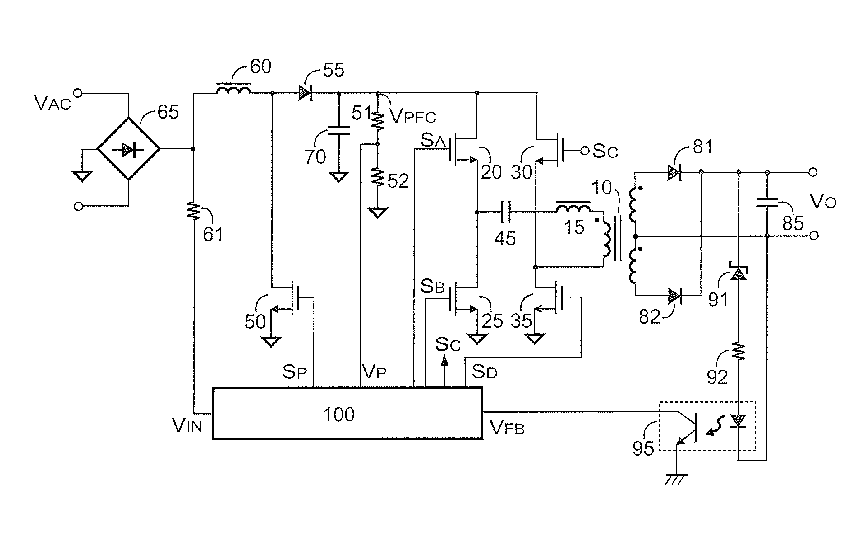
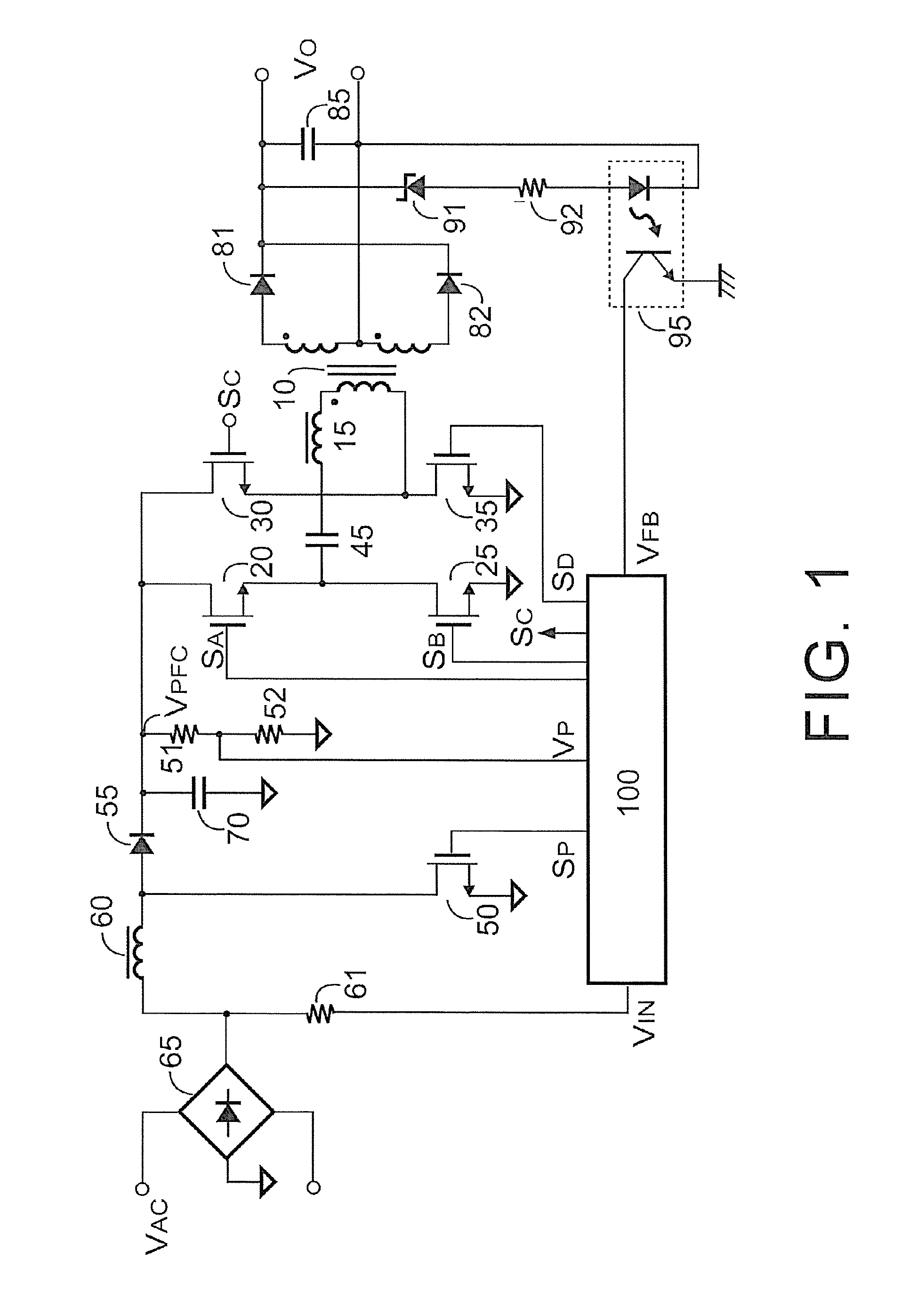
[0022]FIG. 1 shows a power converter in accordance with a preferred embodiment of the present invention. A capacitor 45 and an inductive device (such as a transformer 10 and its parasitic inductor 15) develop a resonant tank. Transistor 20, 25 and 30, 35 develop a full bridge circuit to switch the resonant tank. Two rectifiers 81 and 82 are connected from the secondary winding of the transformer 10 to the output capacitor 85 for generating an output VO at the capacitor 85. A control circuit 100 generates switching signals SA, SB, SC, SD to control the transistors 20, 25, 30, 35 respectively. The switching signal SA is contrast with the switching signal SB. The switching signal SC is contrast with the switching...


PUM


Abstract

A resonant power converter with half bridge and full bridge operations and a method for control thereof are provided. The resonant power converter includes a full bridge circuit, a control circuit and a PFC circuit. The full bridge circuit switches a power transformer in response to switching signals. The control circuit coupled to receive a feedback signal and an input signal generates switching signals. The feedback signal is correlated to the output of the power converter and the input signal is correlated to the input voltage of the full bridge circuit, where the full bridge circuit is operated as a full bridge switching when the input signal is lower than a threshold, and the full bridge circuit is operated as a half bridge switching when the input signal is higher than the threshold. The PFC circuit generates the input voltage of the full bridge circuit.

Description

CROSS-REFERENCE TO RELATED APPLICATION[0001]This application claims the priority benefit of U.S. provisional application Ser. No. 61 / 274,298, filed on Aug. 14, 2009. The entirety of the above-mentioned patent application is hereby incorporated by reference herein and made a part of specification.BACKGROUND OF THE INVENTION[0002]1. Field of the Invention[0003]The present invention relates to a resonant power converter, and more particularly, relates to a resonant power converter with half bridge and full bridge operations and method for control thereof.[0004]2. Description of Related Art[0005]The resonant power converter is a high efficiency power converter. Its prior art can be found in “Switching controller for resonant power converter” by Yang et al., U.S. Pat. No. 7,313,004. The drawback of the resonant power converter is its narrow operation range. It cannot be operated in a wide input voltage range.SUMMARY OF THE INVENTION[0006]The object of the present invention is to provide ...

Claims


Application Information

Patent Timeline
Patent Type & Authority Patents(United States)
IPC IPC(8): G05F1/70
CPCH02M3/3376H02M1/4225H02M2001/0022Y02B70/1491Y02B70/126Y02B70/1433H02M2001/0058H02M2001/007Y02B70/10H02M1/0022H02M1/0058H02M1/007
Inventor YANG, TA-YUNG
Owner SEMICON COMPONENTS IND LLC
Learn More