Oscillator circuit, phase-locked loop circuit, and device

An oscillator, phase-locked loop technology, applied in the field of digital clocks, can solve problems such as poor linearity of voltage-to-current conversion

Inactive Publication Date: 2016-06-29
SHENZHEN PANGO MICROSYST CO LTD
View PDF12 Cites 3 Cited by
  • Summary
  • Abstract
  • Description
  • Claims
  • Application Information

AI Technical Summary

Problems solved by technology

[0007] The invention provides an oscillator circuit, a phase-locked loop circuit and equipment to solve the problem of relatively poor linearity of voltage-to-current conversion in the existing VCO

Method used


Image

  • Oscillator circuit, phase-locked loop circuit, and device
  • Oscillator circuit, phase-locked loop circuit, and device
  • Oscillator circuit, phase-locked loop circuit, and device

Examples


no. 1 example

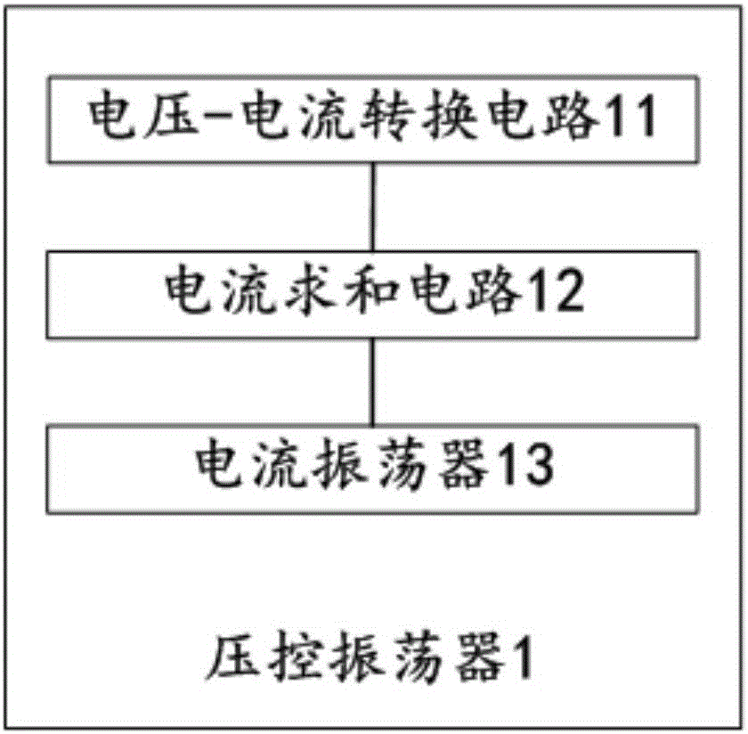
[0031] figure 1 The structure schematic diagram of the oscillator circuit provided for the first embodiment of the present invention is represented by figure 1 It can be seen that in this embodiment, the oscillator circuit 1 provided by the present invention includes: a voltage-current conversion circuit 11, a current summation circuit 12, and a current oscillator 13 connected in sequence, and the voltage-current conversion circuit 11 adopts analog linearization conversion The input voltage is converted into current by means of a method, and output to the current summation circuit 12 , the current summation circuit 12 generates the control current of the high and low dual gain paths according to the input current, and outputs to the current oscillator 13 .

[0032] In some embodiments, the current summation circuit 12 in the above embodiments achieves proportional linear conversion of the input current through parallel connection and proportional size to generate the control c...

no. 2 example

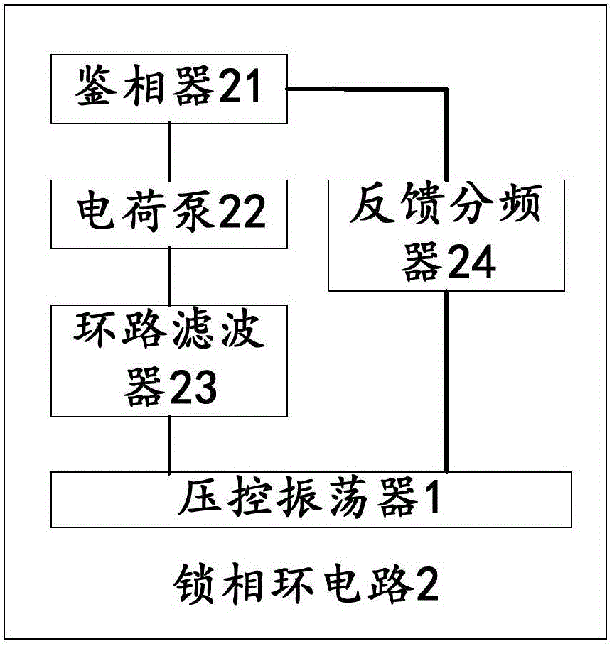
[0042] figure 2 The schematic structural diagram of the phase-locked loop circuit provided for the second embodiment of the present invention, by figure 2 It can be seen that, in this embodiment, the phase-locked loop circuit 2 provided by the present invention includes a phase detector 21, a charge pump 22, a loop filter 23, a feedback frequency divider 24, and a voltage-controlled oscillator provided by the present invention 1. The voltage controlled oscillator 1 and the loop filter 23 are respectively connected to the charge pump 22, the feedback frequency divider 24 is respectively connected to the output terminal of the voltage controlled oscillator 1 and the input terminal of the phase detector 21, and the charge pump 22 is connected with phase detector 21.

[0043] In some embodiments, the loop filter 23 in the above embodiment includes: a high pole generation circuit and a low pole generation circuit, respectively connected to the voltage-current conversion circuit ...

no. 3 example

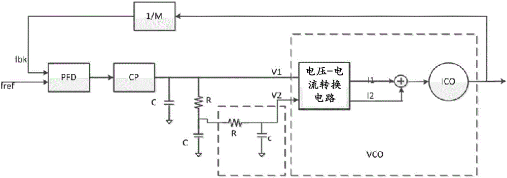
[0048] Such as image 3 As shown, the phase-locked loop circuit of the high and low dual-gain control paths provided by the present embodiment includes: a phase detector (PFD), a charge pump (chargepump), a loop filter (loopfilter), and a voltage-controlled oscillator (VCO) , the feedback divider (1 / M).

[0049] Among them, after the loop filter adopts the conventional second-order filter, it continues to use the first-stage RC low-pass filter to form a low loop bandwidth, and then connects to the VCO high-gain path.

[0050] In the voltage-to-current conversion circuit in the VCO circuit, the Figure 4 The circuit scheme shown, linearizes across the resistors to generate the switching current.

[0051] The voltage-current conversion circuit provided in this embodiment includes a high-gain current conversion circuit and a low-gain current conversion circuit, and the current summation circuit includes a parallel first branch and a second branch, such as Figure 4 Shown:

[...


PUM


Abstract

The invention provides an oscillator circuit, a phase-locked loop circuit and equipment; the oscillator circuit includes: a voltage-current conversion circuit, a current summation circuit and a current oscillator connected in sequence, and the voltage-current conversion circuit adopts analog linearization The conversion method converts the input voltage into a current, which is output to the current summation circuit, and the current summation circuit generates the control current of the high and low dual gain paths according to the input current, and outputs it to the current oscillator. Through the implementation of the present invention, the voltage-current conversion circuit adopts analog linearization technology to generate a more linear conversion current into the current oscillator, improve the linearity of the voltage conversion of the VCO with a high-low dual-gain architecture into a current, and expand the VCO voltage control The effective input range also improves the VCO's common-mode suppression ability of the ground interference on the control line; at the same time, it avoids generating low poles inside the VCO, which solves the existing problem of introducing low poles inside the VCO circuit.

Description

technical field [0001] The invention relates to the field of digital clocks, in particular to an oscillator circuit, a phase-locked loop circuit and equipment. Background technique [0002] In the fields of digital systems and high-speed serial communications, the core circuit PLL (phase locked loop) used as a clock generator is a very important circuit. The clock generated by the phase locked loop is used for data synchronization, parallel data serialization and serialization. At the same time, as there are more and more high-speed serial communication protocol standards and the supported data rate is getting higher and higher, the design challenges for PLL are not only reflected in a wide frequency output range, but also in the timing of the clock. Domain jitter (jitter) has extremely low requirements. [0003] As far as the phase-locked loop used for the clock is concerned, the most sensitive module to noise is the oscillator (oscillator), usually VCO (voltage control lo...

Claims


Application Information

Patent Timeline
Patent Type & Authority Applications(China)
IPC IPC(8): H03L7/099H03L7/093
CPCH03L7/099H03L7/093
Inventor 廖英豪
Owner SHENZHEN PANGO MICROSYST CO LTD
Why Eureka
Try Eureka