

Video clamping circuit with low power consumption and large signal input range
A technology of signal range and clamping circuit, which is applied in the direction of TV, electrical components, color TV, etc., and can solve the problems of limited duration and small input current of the circuit
- Summary
- Abstract
- Description
- Claims
- Application Information
AI Technical Summary
Problems solved by technology
Method used
Image

Examples
Embodiment Construction
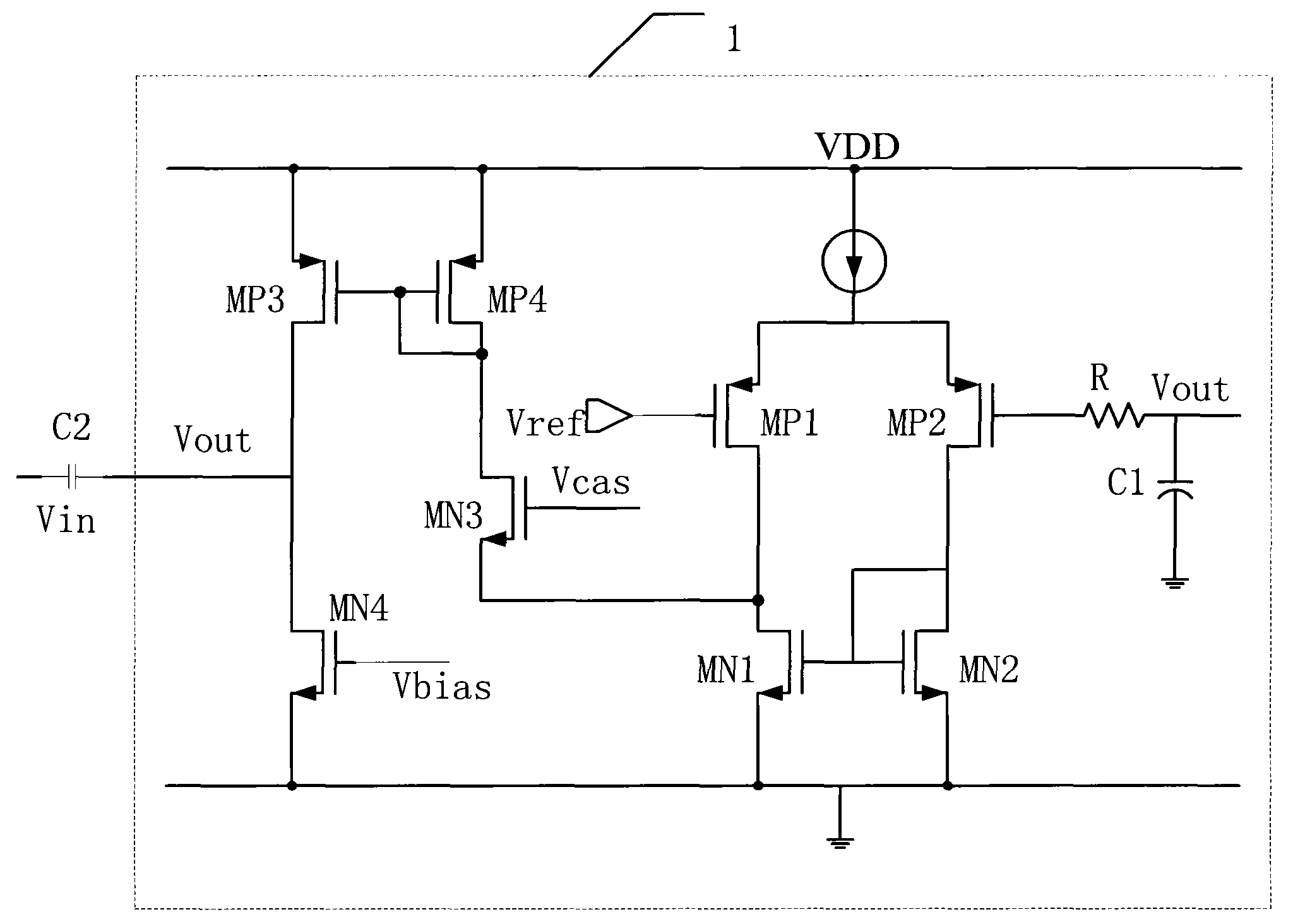
[0015] Such as figure 2 As shown, the transconductance amplifier composed of PMOS1 and PMOS2 pair of tubes, the current mirror amplifier composed of PMOS3 tube and PMOS4 tube, the gate of the PMOS1 is connected to the reference voltage device (Vref), the reference voltage device is connected to the ground, and the PMOS1 The drain of the NMOS3 tube is connected to the source of the NMOS3 tube, and the drain of the NMOS3 tube is connected to the drain of the PMOS4.
[0016] Then the drain of the NMOS1 transistor is connected to the transconductance amplifier, the grid of the NMOS1 transistor is connected to the grid of the NMOS2 transistor, and the grid of the NMOS2 transistor is connected to the drain of the NMOS2 transistor. Such connection makes the NMOS1 and NMOS2 transistors become Constant current source load, NMOS3 is used as a common gate to match the drains of NMOS1 and NMOS2, ensuring that the current flowing through the two NMOS transistors at the same time is the sa...
PUM
 Abstract
Description
Claims
Application Information