This helps you quickly interpret patents by identifying the three key elements:
Problems solved by technology
Method used
Benefits of technology
Problems solved by technology
At this time, if the final fastening connection of the bolt is not confirmed, the possibility of various defects due to insufficient electrical connection will increase.
In addition, when operating in a dark or narrow place, it is sometimes difficult for the operator to confirm the final tightening connection of the bolts
[0004] In particular, since the current solar power generation system represented by the term "mega solar" has a large number of terminal blocks and the like, operations such as using bolts to perform the above-mentioned electrical connection become a considerable burden for the operator. operational burden
Method used
Image
Click on the blue label to locate the original text in one second.
Reading with bidirectional positioning of images and text.
Examples
no. 1 approach
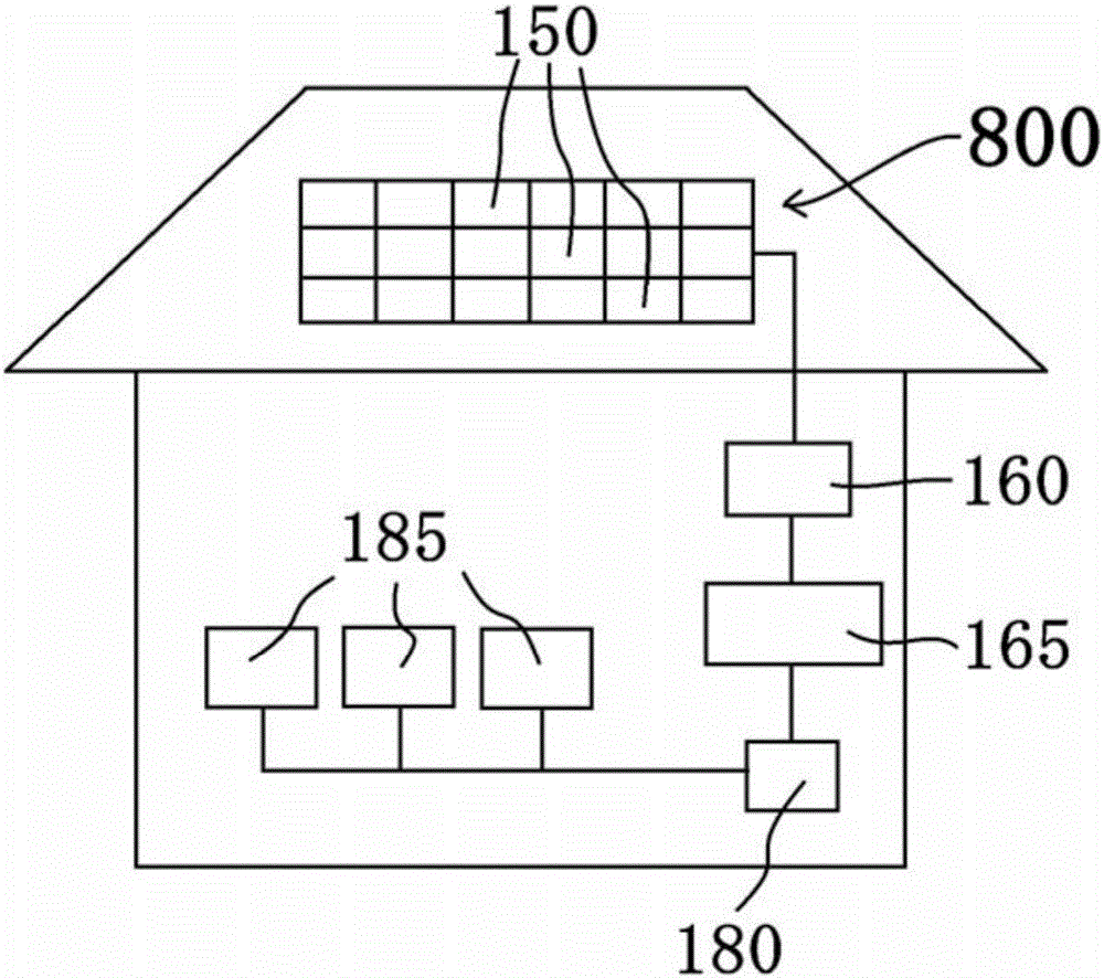
[0096] figure 1 It is a schematic diagram of the structure of the solar power generation system 800 provided with the terminal block 110 of the electrical connection device 100 of this embodiment. Such as figure 1 As shown, the solar power generation system 800 includes, for example, a plurality of solar battery modules 150 installed on the roof of a house, a junction box 160, and a power conditioner 165 that converts DC power generated by the solar battery modules 150 into AC power. In addition, the electric power generated by the solar power generation system 800 is supplied to various electric devices 185 via the switchboard 180 . In the present embodiment, all solar battery modules 150 including a plurality of solar battery cells are arranged on the same surface. In addition, the plurality of solar cell modules 150 are electrically connected in series or in parallel to each other via the electrical connection device 100 .
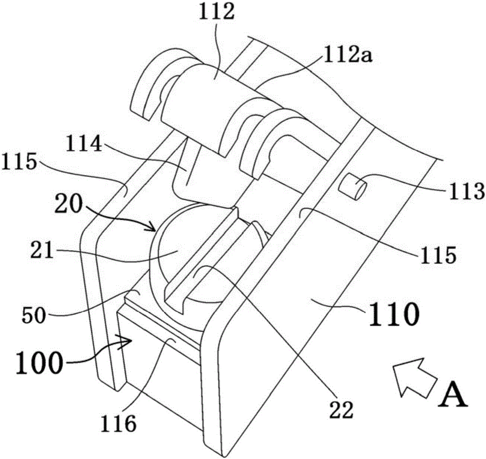
[0097] figure 2 It is a perspective view s...
no. 2 approach
[0115] In this embodiment, the electrical connection device of the first embodiment is identical to the electrical connection device of the first embodiment except that the screw 20 of the first embodiment, the cover body 112 included in the terminal block 110, and the mechanism for changing the biasing force of the coil spring 40 are changed. 100 and the terminal block 110 are the same. Therefore, descriptions of portions overlapping with those of the first embodiment are omitted.
[0116] Figure 12A It is a front view, a left side view, and a vertical cross-sectional view (more specifically, Figure 12A A vertical cross-sectional view of the center of the body portion 224 in the depth direction of the paper). in addition, Figure 12B It is a perspective view showing the shape of the bolt 220 of this embodiment. in addition, Figure 13 to Figure 15 Each is a partial side sectional view for explaining the fastening and connection process of the bolt 220 of the electrical c...
no. 3 approach
[0132] In this embodiment, a bolt 320 is used instead of the bolt 20 in the first embodiment. Figure 20 It is a perspective view corresponding to FIG. 4 showing the shape of the bolt 320 of this embodiment.
[0133] Such as Figure 20 As shown, the bolt 320 of this embodiment has a head 321 and a body 24 having the same structure as the body 24 of the bolt 20 of the first embodiment, and a hole for inserting a screwdriver to rotate the bolt 320 is formed on the head 321 . The slot 322 for a cross-shaped screwdriver. The bolt 320 of this form can also obtain at least some of the effects of the first embodiment.
[0134] However, in order for the operator to visually check the screwing state of the bolt more easily, it is more preferable to use a linear screwdriver groove than to use a cross-shaped screwdriver groove 322 . In addition, of course, in the second embodiment or the fourth embodiment described later, a head having a cross-shaped screwdriver groove 322 formed ther...
PUM
Abstract
An electrical connection device (100) includes a male portion having a head (21) and a body (24), the head (21) being provided with a groove for inserting a driver, and the body (24) being provided with a first guide hole (26a) and a second guide hole (26b), which are formed from the bottom end of the body (24) and which penetrate the body (24) in a spiral manner; a female portion (116) provided with a hole (118) into which the body (24) is inserted; an elastic portion (40) that is disposed on an outer circumference of the body (24) when the body (24) is inserted into the hole (118); and a movable body (30) that is disposed under the elastic portion and that is fitted into the first guide hole (26a) so as to penetrate the same when the body (24) is inserted into the hole (118). A first conductive member (50) and a second conductive member (60) are interposed between the top end of the elastic portion (40) and the head (21). With the movable body (30) fitted in the first guide hole (26a), as the head (21) rotates relative to the hole (118) up to a predetermined rotation angle, the movable body (30) contacting the bottom end of the elastic portion (40) moves upward, whereby the urging force of the elastic portion (40) increases. When the rotation angle of the head (21) relative to the hole (118) exceeds the predetermined rotation angle mentioned above, the movable body (30) fits into an end (29) of the second guide hole (26b), which is provided in a direction for decreasing the urging force and which communicates with the first guide hole (26a), whereby the rotary movement of the movable body (30) relative to the body (24) is suppressed.
Description
technical field [0001] The present invention relates to an electrical connection device, a terminal block provided with the device, a solar power generation system and electric equipment. Background technique [0002] For example, in the wiring connection inside various electrical equipment or the connection between various electrical equipment, such as Figure 24 As shown, the following operations are performed: use the terminal block 900 divided into multiple parts by the walls 90 and 92 , and use bolts 922 to securely connect the wires through the gasket 98 to the conductive plate 94 to perform electrical connection. [0003] At this time, for operators who need to fasten and connect a large number of terminals with bolts or for operators who need to perform this operation for a long time, in order to confirm whether each bolt is reliably fastened and connected, it often takes longer time. In addition, from the viewpoint of operability, the operator needs to perform so-c...
Claims
Application Information
Patent Timeline
Application Date:The date an application was filed.
Publication Date:The date a patent or application was officially published.
First Publication Date:The earliest publication date of a patent with the same application number.
Issue Date:Publication date of the patent grant document.
PCT Entry Date:The Entry date of PCT National Phase.
Estimated Expiry Date:The statutory expiry date of a patent right according to the Patent Law, and it is the longest term of protection that the patent right can achieve without the termination of the patent right due to other reasons(Term extension factor has been taken into account ).
Invalid Date:Actual expiry date is based on effective date or publication date of legal transaction data of invalid patent.

