An Electromagnetic Guidance Pneumatic Valve for Vacuum Suction Fish Pump

A vacuum suction and pneumatic valve technology, which is applied in application, fishing, animal husbandry, etc., can solve the problems of slow opening speed of valve parts, scratches and restrictions on live fish bodies, etc.

Inactive Publication Date: 2020-03-24
FISHERY MACHINERY & INSTR RES INST CHINESE ACADEMY OF FISHERY SCI
View PDF9 Cites 0 Cited by
  • Summary
  • Abstract
  • Description
  • Claims
  • Application Information

AI Technical Summary

Problems solved by technology

However, when the aforementioned vacuum fish suction pump was pumped at the scene, it was found that the opening speed of the valve parts was slow, the control of the valve parts was uncoordinated, and the time difference of air flow was caused by the opening of the valve parts, and the live fish bodies that had been sucked were scratched or cut off by the valve. and other phenomena, affecting the subsequent circulation of live fish
Therefore, the use of the existing vacuum fish suction pump is limited to a certain extent.

Method used


Image

  • An Electromagnetic Guidance Pneumatic Valve for Vacuum Suction Fish Pump
  • An Electromagnetic Guidance Pneumatic Valve for Vacuum Suction Fish Pump
  • An Electromagnetic Guidance Pneumatic Valve for Vacuum Suction Fish Pump

Examples


Embodiment Construction

[0024] The present invention will be further described below in conjunction with specific embodiments and accompanying drawings.

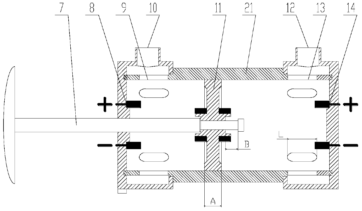
[0025] Such as figure 2 As shown, an electromagnetically guided pneumatic valve for a vacuum fish suction pump specifically includes: a cylinder block 21, a set of front waist holes 9 and a set of rear waist holes 13 are respectively opened at the front and rear ends of the side walls of the cylinder block 21 , the one group of front waist holes 9 and one group of rear waist holes 13 are also connected with the front air port 10 and the rear air port 12 respectively; 14; the valve plug connecting rod 7 extending from the front end of the cylinder block 21 into the cylinder block 21; and the magnet piston 11 located inside the cylinder block 21 and sleeved on the connecting rod shaft of the valve plug connecting rod 7. Wherein, the hole lengths of the front waist hole 9 and the rear waist hole 13 are equal, and the hole length L is the sum of the ...


PUM


Abstract

The invention relates to an electromagnetic guiding pneumatic valve for a vacuum fishing absorbing pump and belongs to the field of fishing engineering. The electromagnetic guiding pneumatic valve for the vacuum fishing absorbing pump comprises a cylinder block, a front magnetic device, a rear magnetic device, a valve plug connecting rod and a magnet piston, wherein a set of front waist holes and a set of rear waist holes are respectively formed at the front and rear ends of a side wall of the cylinder block; the set of front waist holes and the set of rear waist holes are respectively communicated with a front air port and a rear air port; the front magnetic device and the rear magnetic device are arranged on front and rear end faces of the cylinder block; the valve plug connecting rod is inserted into the cylinder block from the front end face of the cylinder block; the magnet piston is located in the cylinder block and is sleeved on a connecting rod shaft of the valve plug connecting rod. The electromagnetic guiding pneumatic valve can be controlled and coordinated, has an automatic sealing ability, is capable of effectively improving the quality of the alive fish and the automatic control capacity and can reduce the energy consumption. When the electromagnetic guiding pneumatic valve is serially connected and matched with a four-way reversing valve, pressure is formed in a fish tank by only one time of reversing through the four-way reversing valve, so that the circulating conversion of the fish absorbing or fish discharging mode can be realized.

Description

technical field [0001] The invention relates to the field of fishery engineering, in particular to an electromagnetic guiding pneumatic valve used for a vacuum fish suction pump. Background technique [0002] China is a large aquatic product breeding country. With the modernization of fishery, vacuum fish suction pumps are used as related supporting equipment for large-scale net cage fishing. Because vacuum fish suction pumps can suck fish / water = 1 / 1, more and more More and more companies are putting it into use. At present, different styles of fish suction pumps have been developed at home and abroad. For example, electric ball valves or gate valves are used to match vacuum fish suction pumps. , the control is complex, causing damage to the fish body. The electromagnetic-guided pneumatic valve is used on the vacuum fish suction pump to solve the above problems. It is easy to control, greatly improves the working efficiency of the fish suction pump, and reduces the support...

Claims


Application Information

Patent Timeline
Patent Type & Authority Patents(China)
IPC IPC(8): A01K79/00
CPCA01K79/00
Inventor 何雅萍石瑞陈寅杰顾海涛钟伟徐英士
Owner FISHERY MACHINERY & INSTR RES INST CHINESE ACADEMY OF FISHERY SCI
Why Eureka
Try Eureka