Valve collet pressure head

A technology of valve lock clamp and pressure head, which is applied in the direction of hand-held tools and manufacturing tools, which can solve the problems of unreasonable operation steps, no convenient and easy-to-use operating tools, and difficult to detect scratches

Active Publication Date: 2017-03-08
ANHUI JIANGHUAI AUTOMOBILE GRP CORP LTD
View PDF4 Cites 3 Cited by
  • Summary
  • Abstract
  • Description
  • Claims
  • Application Information

AI Technical Summary

Problems solved by technology

[0002] When the engine is produced in small batches, it is more economical to press the cylinder head valve lock clip manually, but there is no convenient and easy-to-use operation tool at present
In order to ensure the pre-tightening force of the valve spring used to close the valve, when installing the valve lock clip, it is necessary to ensure that the surface of the valve lock clip is not scratched. The operator generally uses a valve bow or a common sleeve to clean the upper cover of the valve spring. Press and tap to complete the installation of the valve lock clip. Since the tools used are not special tools, the operation steps are not very reasonable. Therefore, the valve stem and the valve lock clip may be damaged during the process of disassembling the valve lock clip. The surface is scratched, but these scratches are not easy to detect, and there will be no faults in the short period of engine operation. Only after a long period of work, the faults can be displayed. At this time, it is irreparable

Method used


Image

  • Valve collet pressure head
  • Valve collet pressure head
  • Valve collet pressure head

Examples


Embodiment Construction

[0020] Embodiments of the present invention are described in detail below, examples of which are shown in the drawings, wherein the same or similar reference numerals designate the same or similar elements or elements having the same or similar functions throughout. The embodiments described below by referring to the figures are exemplary only for explaining the present invention and should not be construed as limiting the present invention.

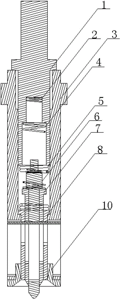
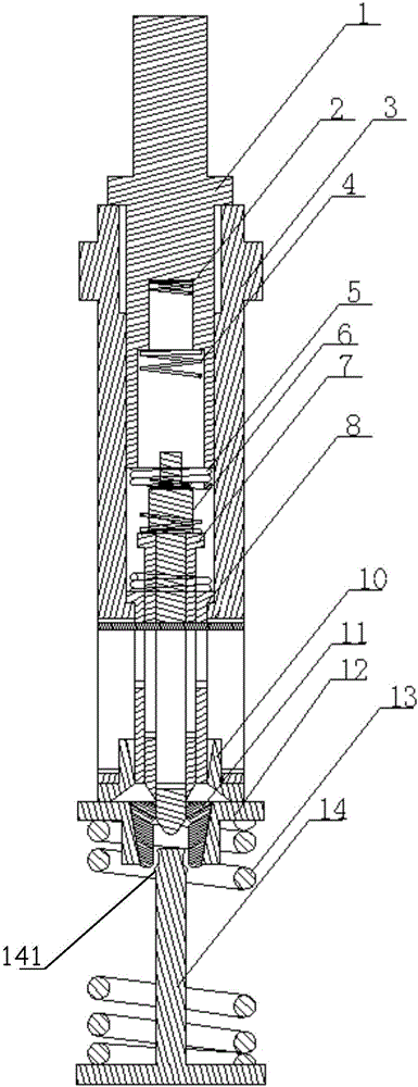
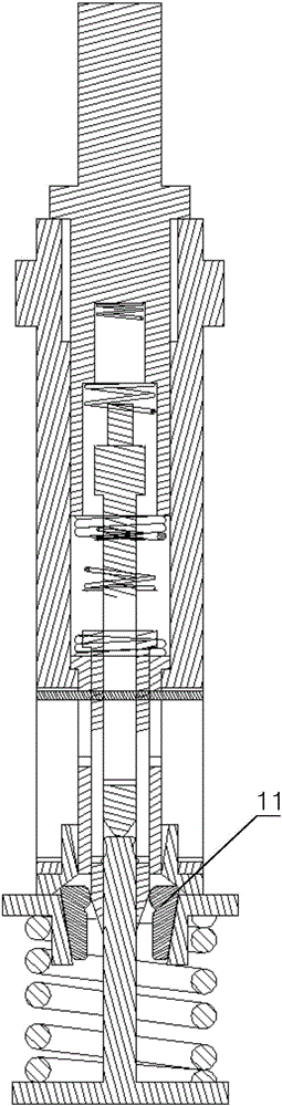
[0021] The invention discloses a valve lock clamp pressure head, which is used to assist in installing the engine valve lock clamp 11, see figure 1 , the valve lock clamp pressure head (hereinafter referred to as the pressure head) includes a housing 3, a guide rod 6, and a guide sleeve 7, each part will be described below.

[0022] continue to see figure 1 , the shell 3 has a hollow space, the guide rod 6 and the guide sleeve 7 are sleeved in the hollow space, one end of the hollow space is a separate end, and the other end is an open ...


PUM


Abstract

The invention discloses a valve collet pressure head. The valve collet pressure head comprises a shell, a guide rod and a guide sleeve. The shell is provided with a hollow space. One end of the hollow space is a sealed end, and the other end of the hollow space is an open end. An elastic element is arranged between the guide rod and the hollow space. The guide rod is movably arranged in the hollow space in a sleeving manner. The guide rod is sleeved with the guide sleeve. The guide sleeve is in sliding fit with the guide rod. In the direction of pointing to the sealed end from the open end, the outer diameter of the outer wall of the bottom of the guide sleeve is increased gradually. By the adoption of the valve collet pressure head, mounting of a valve collet can be completed conveniently and fast, and the valve collet can be protected against scratch.

Description

technical field [0001] The invention relates to an engine preparation aid, in particular to a valve lock clamping head. Background technique [0002] When the engine is produced in small batches, it is more economical to press the cylinder head valve lock clamp manually, but there is no convenient and easy-to-use operation tool at present. In order to ensure the pre-tightening force of the valve spring used to close the valve, when installing the valve lock clip, it is necessary to ensure that the surface of the valve lock clip is not scratched. The operator generally uses a valve bow or an ordinary sleeve to clean the upper cover of the valve spring. Press and tap to complete the installation of the valve lock clip. Since the tools used are not special tools, the operation steps are not very reasonable. Therefore, the valve stem and the valve lock clip may be damaged during the process of disassembling the valve lock clip. The surface is scratched, but these scratches are ...

Claims


Application Information

Patent Timeline
Patent Type & Authority Applications(China)
IPC IPC(8): B25B27/02
CPCB25B27/02
Inventor 王东鑫张亮伊丽莉赵贺金
Owner ANHUI JIANGHUAI AUTOMOBILE GRP CORP LTD
Why Eureka
Try Eureka