Automatic release appliance for optical lens

An optical lens and release technology, applied in glass manufacturing equipment, glass forming, glass pressing, etc., can solve the problems of high mold damage rate, large floor space, waste of water, etc., and achieve less intermediate links and land occupation. Small area and the effect of reducing water waste

Active Publication Date: 2017-03-08
上海银杉工业品销售有限公司
View PDF6 Cites 2 Cited by
  • Summary
  • Abstract
  • Description
  • Claims
  • Application Information

AI Technical Summary

Problems solved by technology

[0008] Therefore, the existing optical lens release equipment has a high mold damage rate during use, which will cause waste, and has a large footprint and waste of water. The present invention proposes a high degree of automation and good optical lens release effect. , high product rate, automatic release equipment for optical lenses that can recycle water resources, etc.

Method used


Image

  • Automatic release appliance for optical lens
  • Automatic release appliance for optical lens
  • Automatic release appliance for optical lens

Examples


Embodiment Construction

[0035] The idea, specific structure and technical effects of the present invention will be further described below in conjunction with the accompanying drawings, so as to fully understand the purpose, features and effects of the present invention.

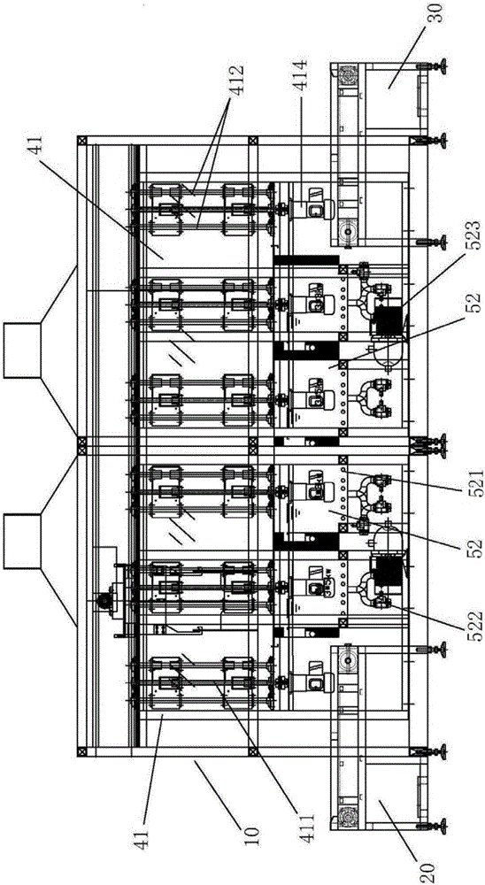
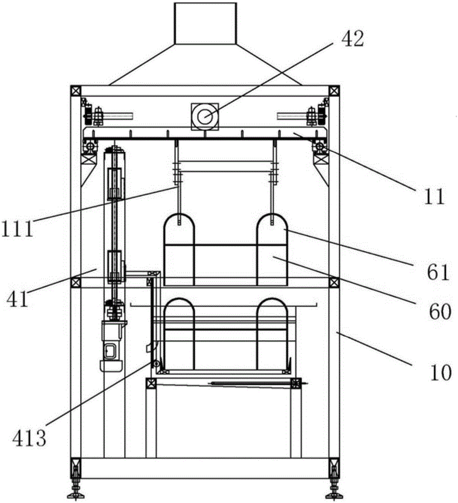
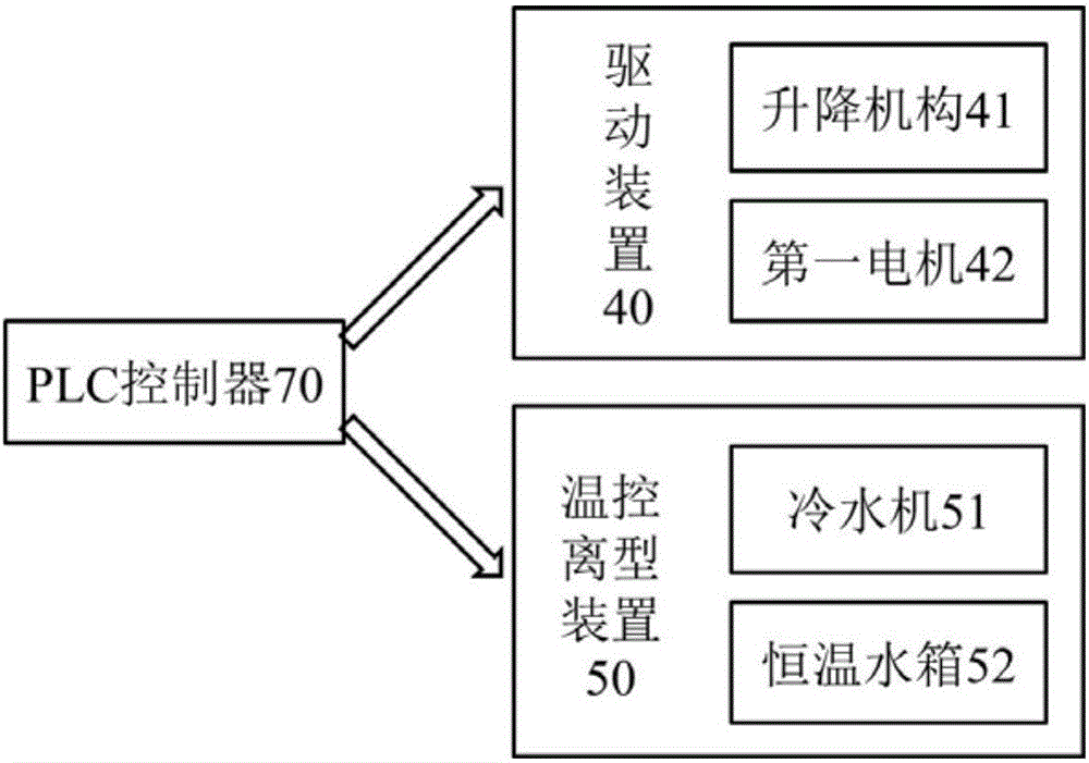
[0036] Such as Figure 1 to Figure 3 As shown, the optical lens automatic release equipment of the present invention includes a frame 10 , a loading table 20 , a feeding table 30 , a driving device 40 , a temperature-controlled release device 50 , a material column 60 and a PLC controller 70 .

[0037] The loading platform 20 and the unloading platform 30 are respectively arranged on both sides of the frame 10, the driving device 40 is installed inside the frame 10, and the constant temperature water tank 52 in the temperature control release device 50 (see description below) ) is arranged in the bottom space in the frame 10; the material column 60 is fixedly connected with the lifting mechanism 41 (described below) in the driving ...


PUM


Abstract

The application aims at providing an automatic release appliance for an optical lens. The automatic release appliance for the optical lens comprises a frame, a charging platform and a discharging platform, wherein the charging platform and the discharging platform are arranged on two sides of the frame respectively; the automatic release appliance for the optical lens also comprises a temperature-controlled release device; the temperature-controlled release device comprises a water cooler and a constant-temperature water tank which is arranged at the bottom of the frame; the water cooler is mounted outside the frame; a circulating water pump used for circulating cold and hot water is arranged between the water cooler and the constant-temperature water tank. Compared with the prior art, the automatic release appliance for the optical lens has the advantages that the temperatures of a heat source and cold water can be controlled precisely and in time, the release rate of the optical lens is high, the loss of a mold is low, a water source is wasted little, the structure is compact, the floor area is less, and the like.

Description

technical field [0001] The present application relates to the technical field of lens manufacturing equipment, in particular to an automatic release equipment for optical lenses. Background technique [0002] The two side structures (A and B molds) of the semi-finished product after one-time curing are called glass molds, and the middle is a transparent optical lens. The process of separating the mold from the optical lens as a whole out of the furnace is generally called the release separation of the lens. . [0003] At present, the release method of most manufacturers is to manually take out the lens and molds A and B from the curing furnace at one time, and tear off the sealing tape; then make a crack in the gap between the optical lens and molds A and B; The whole structure is put into tap water to cool and deform; combined with artificial release device (such as using compressed air blowing to accelerate separation) to separate; finally complete the off-line work of op...

Claims


Application Information

Patent Timeline
Patent Type & Authority Applications(China)
IPC IPC(8): C03B11/12
CPCC03B11/125
Inventor 陈满发王首丰
Owner 上海银杉工业品销售有限公司
Why Eureka
Try Eureka