Combined type ship lock structure

A combined, ship lock technology, used in ship locks, ship lifting devices, climate change adaptation, etc., to achieve the effect of reducing thickness, reducing stacking area, and saving materials

Inactive Publication Date: 2017-03-08
CHANGSHA UNIVERSITY OF SCIENCE AND TECHNOLOGY
6 Cites 0 Cited by

AI-Extracted Technical Summary

Problems solved by technology

For this reason, various measures have been proposed, such as row pile support, rock-socketed double-row support piles, etc. when excavating and constructing adjacent ship locks (see Pan Xuanhe's master's thesis of Changsha University of Science and Technology in 2010 "Foundation with row pile support structure The impact of excavation of pits on adjacent ship locks", Lingwei Master Thesis of Changsha University of Science and Technology in 2013 "Applicatio...

Abstract

A combined type ship lock structure comprises an integrated structure, connecting pieces and sheet piles. The integrated structure is composed of a lock wall and a flat-bottom-shaped bottom plate. The elevation of the top of each sheet pile is between the original ground elevation and the elevation of the top of the lock wall, the elevation of the bottom of each sheet pile is smaller than or equal to the elevation of a foundation surface, and the elevation of the top face of backfill is smaller than or equal to the elevation of the top of the lock wall. During excavation, lateral bracings are adopted, and a built ship lock is very close to the combined type ship lock. Before construction, the sheet piles, the lateral bracings and the connecting pieces are prefabricated. The connecting pieces are fixed to the sheet piles to connect the sheet piles with the integrated structure, then, the bottom plate is constructed, and finally, the lock wall is constructed. By means of the combined type ship lock structure, the amount of reinforced concrete can be reduced, the stress of the integrated structure can also be improved so that the combined type ship lock structure can meet the requirement of higher filling behind a wall better, the excavated volume of earthwork can also be reduced, and a series of problems caused by stacking of abandoned soil can be avoided. The combined type ship lock structure can expand new study fields for design and type selection of building near ship lock structures.

Application Domain

Technology Topic

Image

  • Combined type ship lock structure

Examples

  • Experimental program(1)

Example Embodiment

[0023] The present invention will be further described in detail below with reference to the accompanying drawings and specific embodiments.
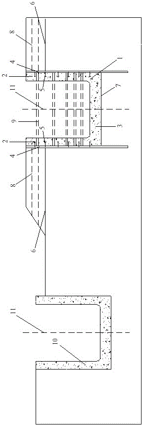
[0024] figure 1 As shown, the present invention is a combined ship lock structure, including an integral structure 1, a lock wall 2, a bottom plate 3, a sheet pile 4, a connecting piece 5, an original ground 6, a foundation surface 7, a backfill 8, and a lateral support 9. , has built ship lock 10, the central axis 11.
[0025] In specific embodiments, as figure 1 The center axis 11 of the combined ship lock of the present invention is very close to the center axis of the existing ship lock 10. The sheet piles 4, connectors 5 and lateral supports 9 of the combined ship lock need to be prefabricated before construction, and the sheet piles 4 are driven by piling. The device hits the preset elevation. The soil between the two rows of sheet piles 4 is excavated on the original ground 6 , and part of the excavated soil can be used as backfill 8 to be filled on the original ground 6 beside the sheet piles 4 . During excavation, the principle of supporting while excavating, and sparse upper and lower density shall be adopted, and lateral supports 9 shall be arranged at suitable positions of sheet piles 4. After the excavation reaches the foundation surface 7, the foundation and the foundation surface 7 are processed. Arrange, install and fix the connector 5 on the sheet pile 4, and then construct the bottom plate 3 of the monolithic structure 1. After the bottom plate 3 is constructed, the bottom lateral support 9 is then evacuated, and the gate wall 2 of the bottom monolithic structure 1 is constructed. , continue to evacuate the lateral support 9 and construct the gate wall 2 until the top of the gate wall 2, so that the sheet pile 4 and the integral structure 1 form a combined integral structure.
[0026] The technical idea and main features of the present invention are shown and described above, and those skilled in the art should be able to understand the content of the present invention and implement it accordingly. The above examples and descriptions are only for illustrating the basic idea and basic implementation steps of the present invention, and do not limit the protection scope of the present invention. Under the premise of not departing from the spirit and scope of the present invention, the present invention will also have various changes and improvements, and these changes and improvements all fall within the scope of the claimed invention. The claimed scope of the present invention is determined by the appended claims. and its equivalents.

PUM

no PUM

Description & Claims & Application Information

We can also present the details of the Description, Claims and Application information to help users get a comprehensive understanding of the technical details of the patent, such as background art, summary of invention, brief description of drawings, description of embodiments, and other original content. On the other hand, users can also determine the specific scope of protection of the technology through the list of claims; as well as understand the changes in the life cycle of the technology with the presentation of the patent timeline. Login to view more.

Similar technology patents

Connection type U disk

InactiveCN103065666AReduce storage areaEasy to carryDigital storageEngineeringAccess port
Owner:苏州久三智能科技有限公司

Placing rack for photovoltaic laminated part

PendingCN113148371AReduce risk of crackingReduce storage areaRigid containersInternal fittingsStructural engineeringMechanical engineering
Owner:江苏彩虹永能新能源有限公司

Classification and recommendation of technical efficacy words

  • Reduce width
  • Reduce storage area

Power semiconductor device

ActiveUS20080169526A1Reduce widthSuperior long-term forward blocking voltage capability reliabilityThyristorPower semiconductor devicePolycrystalline silicon
Owner:FUJI ELECTRIC CO LTD

Mitral valve leaflet clip

InactiveUS20140039607A1Reduce widthSuture equipmentsHeart valvesTissue fixingSurgery
Owner:ST JUDE MEDICAL CARDILOGY DIV INC

Inulin preparing method taking dried jerusalem artichoke as raw material

ActiveCN103044579AReduce storage areaEasy to storeIonActivated carbon
Owner:YANTAI INST OF COASTAL ZONE RES CHINESE ACAD OF SCI

ROM (Read Only Memory) and layout thereof

Owner:苏州兆芯半导体科技有限公司

Bitmap storage method

ActiveCN104793897AReduce storage areaReduce the chance of problemsInput/output to record carriersBit pairingBitmap
Owner:武汉神州数码云科网络技术有限公司

Image processing method, program thereof, and image processing apparatus

InactiveUS20090195803A1Decrease in drawing speed can be suppressedReduce storage areaDigitally marking record carriers2D-image generationSoftwareRaster graphics
Owner:SEIKO EPSON CORP
Why Eureka
Try Eureka