Piston cooling nozzle control method and system

A technology of piston cooling nozzles and control methods, which is applied in liquid cooling, engine cooling, engine components, etc., and can solve problems such as increased fuel consumption

Active Publication Date: 2017-03-08
GREAT WALL MOTOR CO LTD
View PDF8 Cites 20 Cited by
  • Summary
  • Abstract
  • Description
  • Claims
  • Application Information

AI Technical Summary

Problems solved by technology

[0005] In view of this, the present invention aims to propose a piston cooling nozzle control method to

Method used


Image

  • Piston cooling nozzle control method and system
  • Piston cooling nozzle control method and system
  • Piston cooling nozzle control method and system

Examples


Embodiment 1

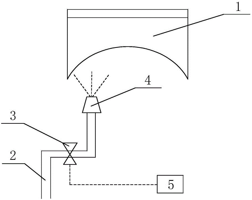
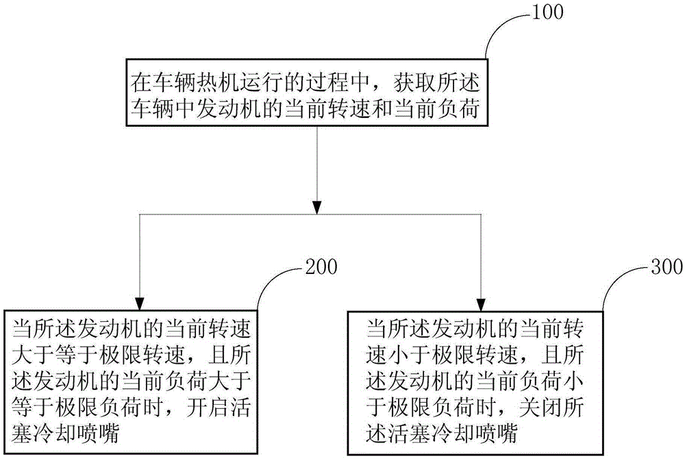
[0068] see figure 1 and figure 2 , an embodiment of the present invention provides a piston cooling nozzle control method, including:

[0069] Step 100, during the warm-up operation of the vehicle, obtain the current rotational speed and current load of the engine in the vehicle;

[0070] Step 200, when the current speed of the engine is greater than or equal to the limit speed, and the current load of the engine is greater than or equal to the limit load, turn on the piston cooling nozzle 4;

[0071] Step 300, when the current speed of the engine is less than the limit speed and the current load of the engine is less than the limit load, close the piston cooling nozzle 4;

[0072] Among them, the limit speed is the speed of the engine when the piston 1 of the engine is at the thermal load limit (reaching the thermal load limit of the piston 1 means that the piston 1 may cause the engine to knock), and the limit load is that the piston 1 is at the thermal load limit. Engin...

Embodiment 2

[0088]Embodiment 2 of the present invention provides a piston cooling nozzle control system, which is controlled by the piston cooling nozzle control method provided in Embodiment 1. The piston cooling nozzle control system includes a control unit 6, and the control unit 6 is used for: in the process of vehicle heat engine operation Among them, when the current speed of the engine is greater than or equal to the limit speed, and the current load of the engine is greater than or equal to the limit load, the piston cooling nozzle 4 is opened; when the current speed of the engine is less than the limit speed, and the current load of the engine is less than the limit load, the piston is closed Cooling nozzle 4; Wherein, the limit speed is the speed of the engine when the piston 1 is at the thermal load limit, and the limit load is the load of the engine when the piston 1 is at the thermal load limit.

[0089] During specific implementation, lubricating oil can be used as the coolan...


PUM


Abstract

The invention provides a piston cooling nozzle control method and system, relates to the technical field of vehicles, and aims to solve the problem that the oil consumption of a vehicle is increased due to the too low temperature of a piston. The piston cooling nozzle control method comprises the following steps: acquiring the current rotational speed and the current load of an engine in the vehicle during heat-engine running of the vehicle; opening a piston cooling nozzle when the current rotational speed of the engine is higher than or equal to the ultimate rotational speed and when the current load of the engine is higher than or equal to the ultimate load; and closing the piston cooling nozzle when the current rotational speed of the engine is lower than the ultimate rotational speed and when the current load of the engine is lower than the ultimate load, wherein the ultimate rotational speed is set to the rotational speed of the engine acquired when the piston of the engine reaches the limit of heat load and the ultimate load is set to the load of the engine acquired when the piston reaches the limit of heat load. The piston cooling nozzle control method provided by the invention is used for lowering the oil consumption of the vehicle.

Description

technical field [0001] The invention relates to the technical field of automobiles, in particular to a method and system for controlling a piston cooling nozzle. Background technique [0002] With the development of the automobile industry, in order to reduce the weight of the whole vehicle, the weight and size of the engine are getting smaller and smaller, which requires the continuous improvement of the engine power (liter power means the working capacity per unit cylinder working volume, the greater the power The greater the power generated per unit cylinder working volume), the liter power of the engine directly affects the heat load of the engine. High, the temperature of the piston is too high may cause the engine to knock. [0003] In order to reduce the temperature of the piston, most engines are provided with a piston cooling nozzle near the piston at present, and the piston cooling nozzle is communicated with the lubricating oil passage, and the lubricating oil pa...

Claims


Application Information

Patent Timeline
IPC IPC(8): F01P3/06
Inventor 李怀军卢维伟张翠翠
Owner GREAT WALL MOTOR CO LTD
Why Eureka
Try Eureka