Water tank assembly and dehumidifier

A dehumidifier and water tank technology, applied in the field of water tank components and dehumidifiers, can solve the problems of difficult disassembly and assembly of a drainage structure, and achieve the effect of improving reliability

Inactive Publication Date: 2017-03-08
GREE ELECTRIC APPLIANCES INC
View PDF5 Cites 7 Cited by
  • Summary
  • Abstract
  • Description
  • Claims
  • Application Information

AI Technical Summary

Problems solved by technology

[0005] The main purpose of the present invention is to provide a water tank assembly and a dehumidifier to solve the problem that the drainage structure of the water tank of the dehumidifier in the prior art is not easy to disassemble

Method used


Image

  • Water tank assembly and dehumidifier
  • Water tank assembly and dehumidifier
  • Water tank assembly and dehumidifier

Examples


Embodiment Construction

[0025] It should be noted that, in the case of no conflict, the embodiments of the present invention and the features in the embodiments can be combined with each other. The present invention will be described in detail below with reference to the accompanying drawings and examples.

[0026] In order to enable those skilled in the art to better understand the solutions of the present invention, the following will clearly and completely describe the technical solutions in the embodiments of the present invention in conjunction with the drawings in the embodiments of the present invention. Obviously, the described embodiments are only It is an embodiment of a part of the present invention, but not all embodiments. Based on the embodiments of the present invention, all other embodiments obtained by persons of ordinary skill in the art without making creative efforts shall fall within the protection scope of the present invention.

[0027] It should be noted that the terms "first...


PUM


Abstract

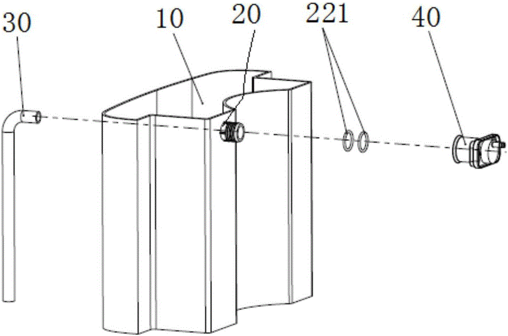
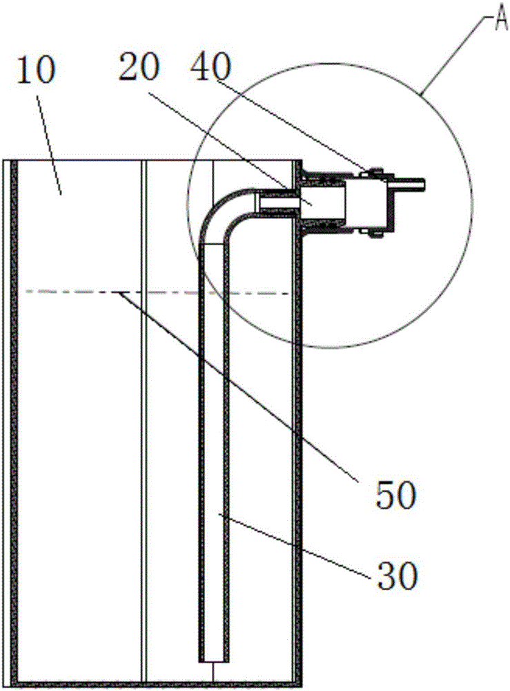
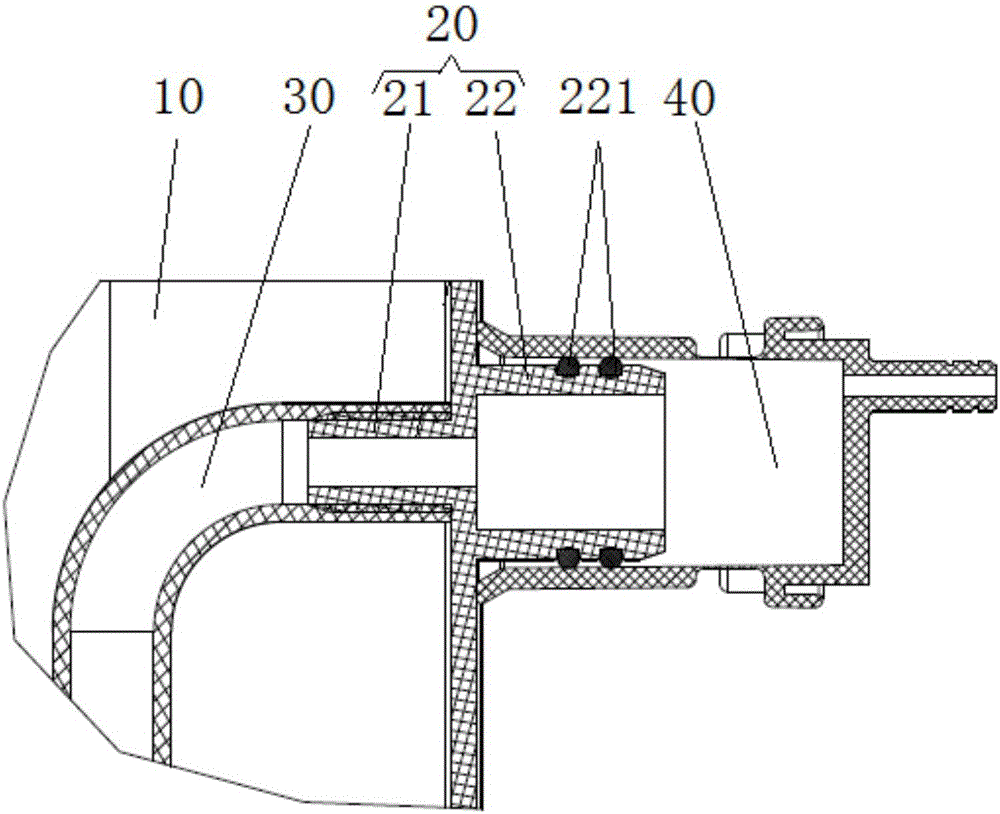
The invention provides a water tank assembly and a dehumidifier. The water tank assembly comprises a water tank, a first drainage connector, a water guiding pipe and a second drainage connector. The water tank is provided with an opening used for pouring of water. The first drainage connector is arranged in the middle-upper position of the water tank, the water guiding pipe is arranged inside the water tank and connected with the first drainage connector, and the second drainage connector is arranged outside the water tank, detachably connected with the first drainage connector and used for being connected with drainage equipment. When manual drainage of the water tank is needed, the water tank can be moved to directly pour water from the opening in the water tank only by disconnecting the first drainage connector and the second drainage connector. Due to the fact that the first drainage connector is arranged in the middle-upper position of the water tank, water cannot overflow from the first drainage connector after the first drainage connector and the second drainage connector are disconnected only by enabling the water level to be lower than the first drainage connector.

Description

technical field [0001] The invention relates to the technical field of dehumidifiers, in particular to a water tank assembly and a dehumidifier. Background technique [0002] Dehumidifiers are also known as dehumidifiers, dryers, and dehumidifiers. They can generally be divided into two categories: civil dehumidifiers and industrial dehumidifiers, and belong to a part of the air-conditioning family. Usually, a conventional dehumidifier consists of a compressor, a heat exchanger, a fan, a water tank, a casing and a controller. Its working principle is: the humid air is drawn into the machine by the fan, and passes through the heat exchanger. At this time, the water molecules in the air condense into water droplets, and the dried air after treatment is discharged outside the machine. This cycle keeps the indoor humidity at a suitable level. Relative humidity. [0003] The condensed water generated during the normal operation of the dehumidifier is collected in the water tank...

Claims


Application Information

Patent Timeline
Patent Type & Authority Applications(China)
IPC IPC(8): F24F13/22
CPCF24F13/222
Inventor 黄治华胡树锋林强练黄海强张顺祥
Owner GREE ELECTRIC APPLIANCES INC
Why Eureka
Try Eureka