Measuring method and system for frequency response of electro-optical modulator

An electro-optic modulator and frequency response technology, applied in the direction of frequency measurement devices, etc., can solve the problems that the frequency response of the phase modulator cannot be measured, it is complicated and difficult to implement, and the matching requirements are relatively high, so as to achieve high test efficiency, good stability, and line The effect of simple structure

Active Publication Date: 2017-03-08
NANJING UNIV OF AERONAUTICS & ASTRONAUTICS
View PDF9 Cites 22 Cited by
  • Summary
  • Abstract
  • Description
  • Claims
  • Application Information

AI Technical Summary

Problems solved by technology

Many scientific researchers have done in-depth research on this, for example, the traditional light wave component analysis method, but this method has relatively high requirements for matching and has certain limitations
[0005] At the same time, the traditional light wave component analysis method cannot measure the frequency response of the phase modulator. For this, Bao Xiaobin et al. proposed to measure one of the important parameters of the phase modulator in the article 'High frequency measurement and characterization on high-speed electrochemi

Method used


Image

  • Measuring method and system for frequency response of electro-optical modulator
  • Measuring method and system for frequency response of electro-optical modulator
  • Measuring method and system for frequency response of electro-optical modulator

Examples


Embodiment

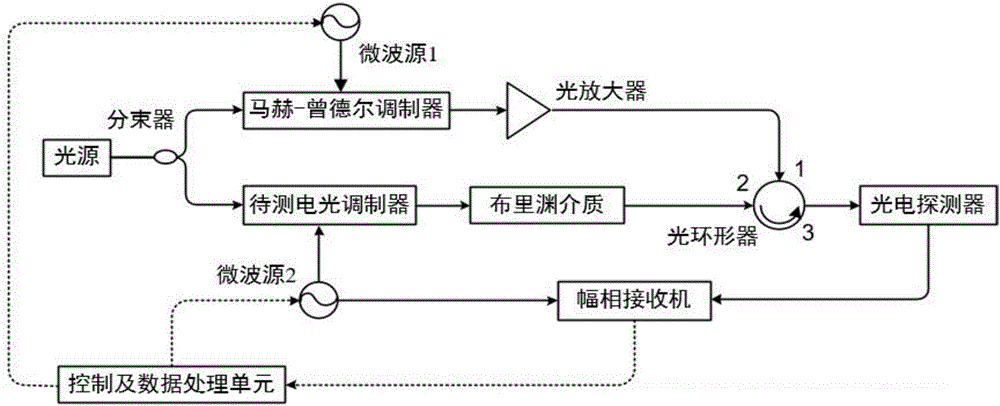
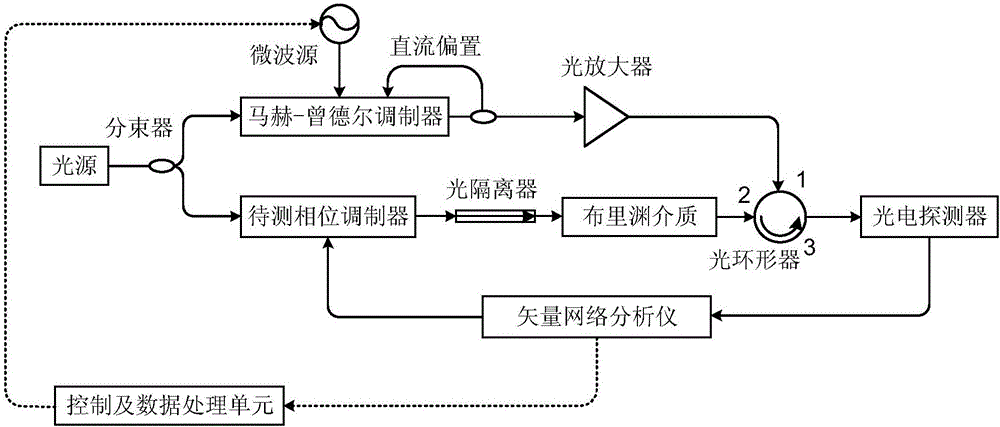
[0034] Such as figure 2 As shown, an embodiment of the electro-optic modulator frequency response measurement system of the present invention. The system includes: light source, microwave source, vector network analyzer, bias point controller, Mach-Zehnder modulator, 40GHz phase modulator to be tested, photodetector, Brillouin gain medium, optical amplifier, optical isolator , optical beam splitter, optical circulator and control and data processing unit. In this embodiment, a vector network analyzer is selected, which has the functions of the microwave source 2 and the amplitude and phase receiver at the same time. The specific implementation idea is to use an optical beam splitter to divide the optical carrier signal output by the laser into upper and lower channels. The upper channel uses a Mach-Zehnder modulator to modulate the microwave signal output by the microwave source to the optical carrier, supplemented by an appropriate DC bias. Generate a double sideband signa...


PUM


Abstract

The invention discloses a measuring method and system for frequency response of an electro-optical modulator. A light beam splitter divides optical carrier signals into an upper path and a lower path; in the upper path, a Mach-Zehnder modulator modulates microwave signals output by a microwave source 1 to optical carrier waves, and double-side-band signals which inhibit the carrier waves are generated, and serve as pumping signals after being amplified; and in the lower path, the electro-optical modulator to be measured modulates microwave signals output by a microwave source 2 to optical carrier waves, and double-side-band signals are generated. The frequencies of the microwave source 1 and the microwave source 2 are adjusted, so that the double-side-band signals output by the electro-optical modulator to be measured form single-side-band signals in a Brillouin medium. A photoelectric detector converts the single-side-band signals into electric signals, an amplitude-phase receiver extracts amplitude and phase information from the electric signals, and combined response of the electro-optical modulator to be measured and the photoelectric detector are obtained; and the frequency response of the electro-optical modulator to be measured is obtained by removing the frequency response of the photoelectric detector.

Description

technical field [0001] The present invention relates to a frequency response measurement method and measurement system of an electro-optic modulator, in particular to a method and system for measuring the frequency response of an electro-optic modulator based on the stimulated Brillouin scattering effect, belonging to the technical field of electro-optical device measurement and microwave photonics . Background technique [0002] Optical fiber communication has many advantages such as anti-electromagnetic interference, anti-corrosion, light weight, and large capacity, so it is widely used in many fields such as high-energy physics, anti-nuclear radiation communication systems, submarines, warships, aircraft, missile control communication systems, and the Internet. At present, optical fiber communication is developing in the direction of high speed, high efficiency, large capacity and long distance optical fiber transmission. As the degree of informatization becomes higher a...

Claims


Application Information

Patent Timeline
IPC IPC(8): G01R23/02
CPCG01R23/02
Inventor 薛敏潘时龙衡雨清
Owner NANJING UNIV OF AERONAUTICS & ASTRONAUTICS
Why Eureka
Try Eureka