Touch display device and electronic apparatus

A technology for touch display and electronic devices, applied in circuits, electrical components, electric solid devices, etc., can solve problems such as poor visibility

Inactive Publication Date: 2017-03-08
TOP VICTORY INVESTMENTS
View PDF14 Cites 5 Cited by
  • Summary
  • Abstract
  • Description
  • Claims
  • Application Information

AI Technical Summary

Problems solved by technology

[0009] The purpose of the present invention is to solve the problem of poor outdoor visibility of frame-mounted touch display devices under the influence of strong ambient light in the prior art

Method used


Image

  • Touch display device and electronic apparatus
  • Touch display device and electronic apparatus
  • Touch display device and electronic apparatus

Examples


Embodiment Construction

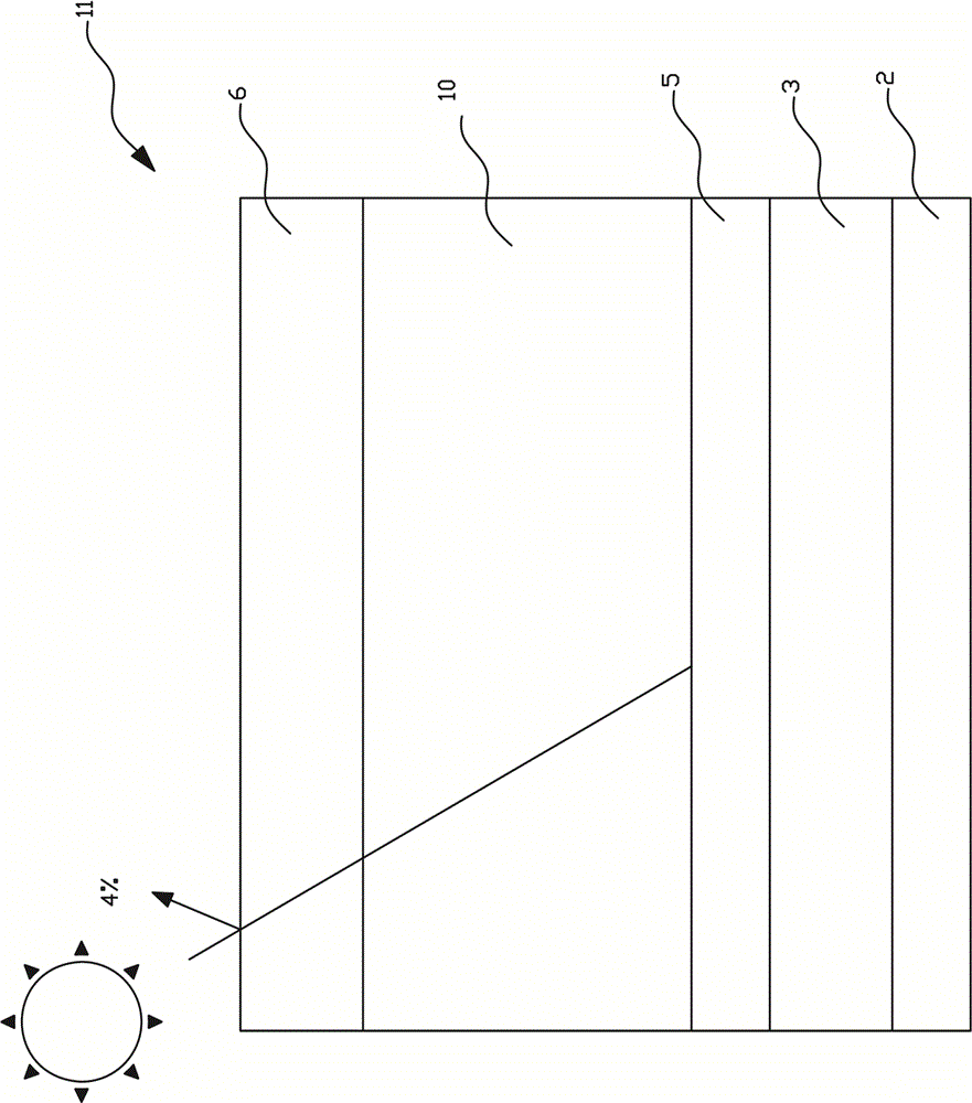
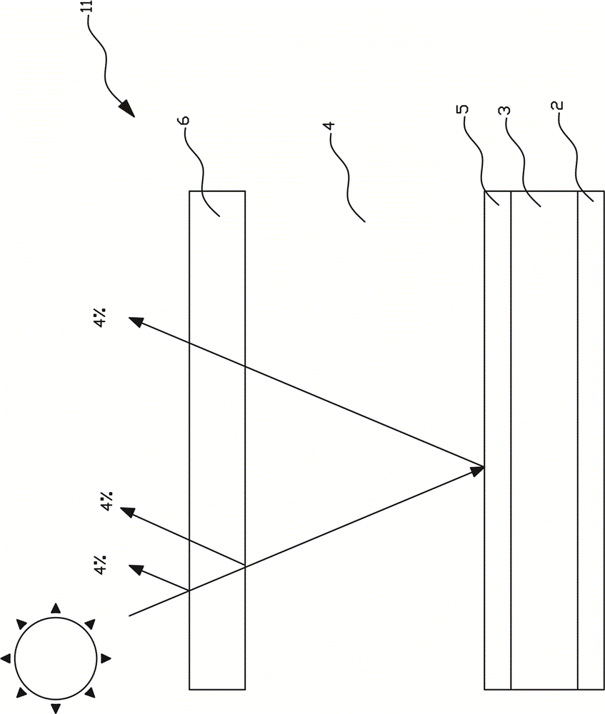
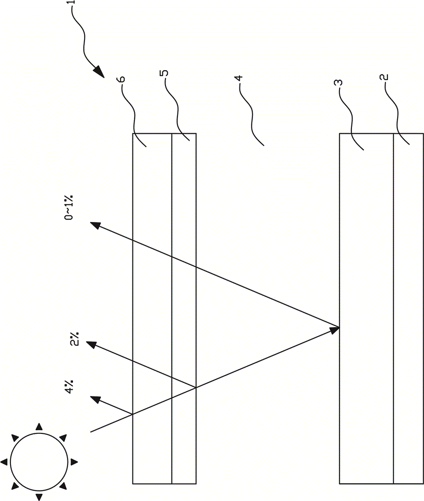
[0053] Please refer to Figures 3 to 10 . The present invention relates to a touch display device, which comprises: a first polarizer 2; a display plate 3 arranged on the first polarizer 2; a gap 4 arranged on the display plate 3; and a second polarizer The sheet 5 is arranged on the gap 4 .

[0054] In an embodiment of the present invention, wherein the first polarizer 2 has a first polarization axis, the second polarizer 5 has a second polarization axis, and the first polarization axis matches the second polarization axis to display images . Two polarizers with mismatched polarization axes cannot display images. For example, if the display panel is a traditional transmissive TN or VA or FFS liquid crystal display panel or an IPS liquid crystal display panel, usually the second polarization axis is perpendicular to the first polarization axis.

[0055] In an embodiment of the present invention, the first polarizer 2 is a linear polarizer or a circular polarizer. Among th...


PUM

PropertyMeasurementUnit
reflectanceaaaaaaaaaa
refractive indexaaaaaaaaaa

Abstract

The invention provides a touch display device used for solving the problem that the outdoor visibility of a frame sticking type touch display device is poor under the influence of strong ambient light in the prior art. The invention relates to a touch display device comprising a first polarizer (2); a display panel (3) arranged on the first polarizer; a gap (4) arranged on the display panel; and a second polarizer (5) arranged on the gap. The touch display device further comprises a cover plate, wherein the cover plate is arranged on the outermost side face of the touch display device relative to the first polarizer. The invention further relates to an electronic apparatus comprising the touch display device described above.

Description

technical field [0001] The present invention relates to a display device, and in particular to a touch display device and an electronic device. Background technique [0002] Please see figure 1 and figure 2 , figure 1 is a structural diagram of a surface-mounted touch display device in the prior art, and figure 2 It is a structural diagram of a frame-mounted touch display device in the prior art. [0003] The touch display device in the prior art includes a touch panel (Touch Panel, TP) and a display module (Display Module). Bonding) is the main bonding technology, in which the cost of the frame-mounted touch display device is lower than that of the surface-mounted one. [0004] The aforesaid touch panels include capacitive, resistive, or electromagnetic induction, especially capacitive. [0005] figure 1 A surface-mounted touch display device 11 in the prior art, its structure includes from top to bottom: a touch panel 6, a solid optical glue (Optically Clear Adhes...

Claims


Application Information

Patent Timeline
Patent Type & Authority Applications(China)
IPC IPC(8): G06F3/041G02F1/1333
CPCG02F1/13338G06F3/0412G02F1/13312G02F1/133331G02F1/133541H10K59/40G06F3/041
Inventor 王文俊周建良吴易骏王伯贤
Owner TOP VICTORY INVESTMENTS
Why Eureka
Try Eureka