Light collimator and manufacturing method thereof

A manufacturing method and light collimation technology, applied in optics, instruments, optical components, etc., can solve the problems of process tolerance, difficulty in aligning light absorption patterns, affecting the quality of image acquisition, etc., so as to reduce interface reflection, improve manufacturing output, and avoid scratches. effect of injury

Inactive Publication Date: 2018-10-09
FOCALTECH SMART SENSORS CO LTD
View PDF10 Cites 1 Cited by
  • Summary
  • Abstract
  • Description
  • Claims
  • Application Information

AI Technical Summary

Problems solved by technology

However, due to process tolerances, it is difficult to align the light-absorbing patterns on the two surfaces of the transparent substrate
In addition, since the interface between the light-transmitting substrate and the light-absorbing pattern is a smooth surface, it is easy to generate interface reflection, which affects the image quality.
In addition, the light-absorbing patterns on the two surfaces of the light-transmitting substrate are easily scratched, which affects the manufacturing yield

Method used


Image

  • Light collimator and manufacturing method thereof
  • Light collimator and manufacturing method thereof
  • Light collimator and manufacturing method thereof

Examples


Embodiment Construction

[0037] Reference will now be made in detail to the exemplary embodiments of the present invention, examples of which are illustrated in the accompanying drawings. Wherever possible, the same reference numbers will be used in the drawings and description to refer to the same or like parts.

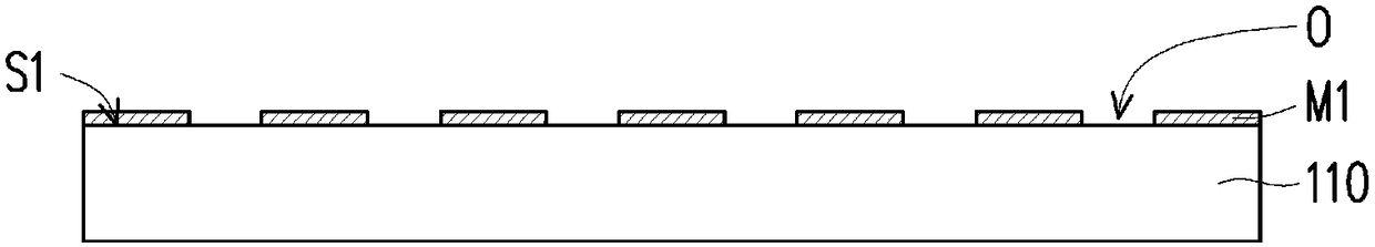
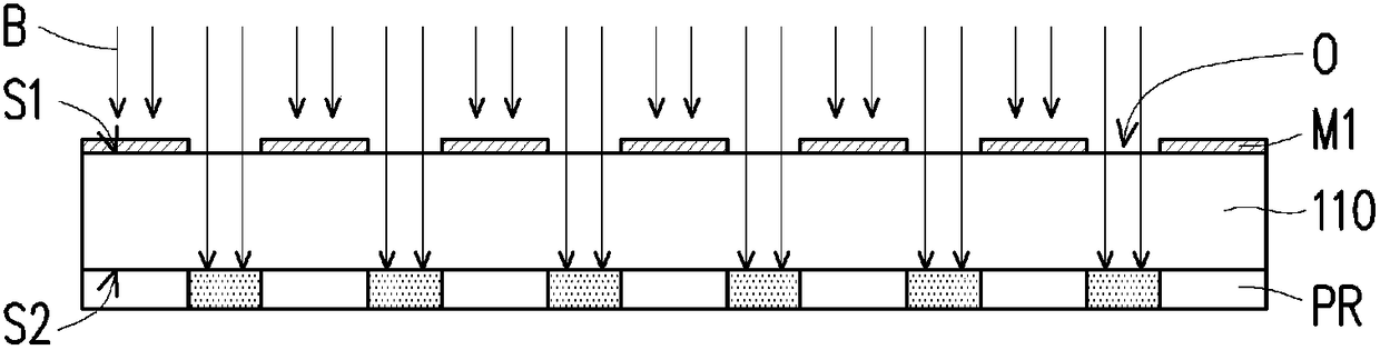
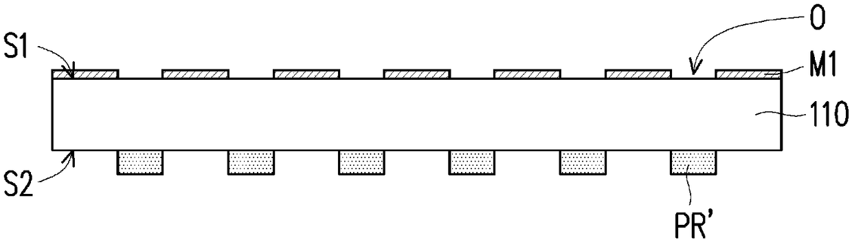
[0038] Figure 1A to Figure 1H is a schematic cross-sectional view of the manufacturing process of the optical collimator according to the embodiment of the present invention. Please refer to Figure 1A , forming a metal mask M1 on the surface S1 of the transparent substrate 110 . The metal mask M1 has a plurality of openings O through which light beams can pass, and the openings O expose the region where the depression to be formed is located (refer to Figure 1F The relative position of the opening O and the depression C). The transparent substrate 110 is, for example, a glass substrate, and the material of the metal mask M1 is, for example, Chromium, but not limited thereto. The meth...


PUM


Abstract

The invention provides a light collimator and a manufacturing method thereof. The light collimator comprises a light transmitting substrate and a plurality of light absorbing patterns, wherein two opposite surfaces of the light transmitting substrate are respectively provided with a plurality of depressions which are arranged at intervals, and the depressions on the two surfaces are mutually aligned; and the light absorbing patterns are arranged in the depressions. The light collimator and the manufacturing method thereof provided by the invention can enable the light absorbing patterns on thetwo opposite surfaces of the light transmitting substrate to be mutually aligned, reduce the interface reflection and improve a problem of scratches.

Description

technical field [0001] The invention relates to an optical element and its manufacturing method, and in particular to a light collimator and its manufacturing method. Background technique [0002] Types of biometric identification include face, voice, iris, retina, vein, fingerprint and palmprint recognition, etc. Since each person's fingerprint is unique, and the fingerprint is not easy to change with age or health status, the fingerprint identification device has become the most popular biometric identification device at present. According to different sensing methods, fingerprint identification devices can be classified into optical type and capacitive type. When the capacitive fingerprint recognition device is assembled in an electronic product (such as a mobile phone, a tablet computer), a protective element (cover lens) is often provided above the capacitive fingerprint recognition device. Generally speaking, additional processing (such as drilling or thinning) of th...

Claims


Application Information

Patent Timeline
Patent Type & Authority Applications(China)
IPC IPC(8): G02B27/30
CPCG02B27/30
Inventor 张育儒钟炜竣王炯翰谢明哲
Owner FOCALTECH SMART SENSORS CO LTD
Why Eureka
Try Eureka