Supercharge Your Innovation With Domain-Expert AI Agents!

A Component Locating Method Based on Template Matching

A positioning method and template matching technology, applied in the field of image processing, can solve the problems of poor versatility and low illumination robustness, and achieve the effect of stability and high performance

Active Publication Date: 2019-05-14
HARBIN INST OF TECH
View PDF7 Cites 0 Cited by
  • Summary
  • Abstract
  • Description
  • Claims
  • Application Information

AI Technical Summary

Problems solved by technology

[0004] The present invention proposes a component positioning method based on template matching in order to solve the problems of poor versatility and low robustness to illumination in existing patch component positioning algorithms

Method used


Image

  • A Component Locating Method Based on Template Matching
  • A Component Locating Method Based on Template Matching
  • A Component Locating Method Based on Template Matching

Examples


specific Embodiment approach 1

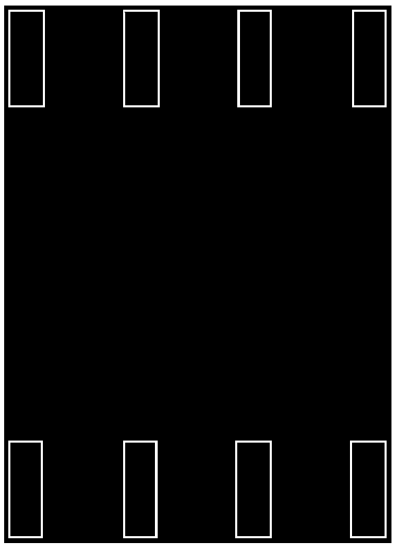
[0056] Specific implementation mode 1. Combination figure 1 Describe this embodiment, a template matching-based component positioning method described in this embodiment, the specific steps of the method are:

[0057] Step 1. Create a template image for the component to be positioned. The pixel gray value of the pin edge of the component in the template image is a, and the background gray value is 0; a is a positive integer; the template image is as follows: figure 1 shown;

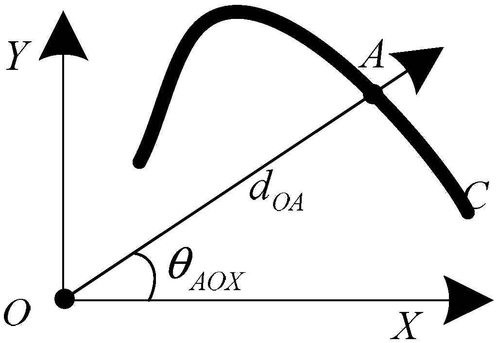
[0058] Step 2, taking the center of the template image as the origin to establish a rectangular coordinate system to obtain the vector field of the template image;

[0059] The information of the template image includes the distance between the edge point of the template image and the coordinate origin and the angle between the line between the edge point of the template image and the coordinate origin and the Cartesian coordinate system X axis of the template image;

[0060] Step 3, use an industrial...

specific Embodiment approach 2

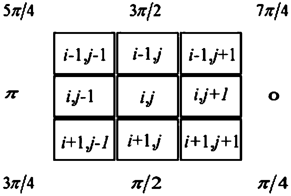
[0078] Specific embodiment 2. This embodiment is a further description of a component positioning method based on template matching described in specific embodiment 1. The specific steps of the method are: in step 2, establish a right angle with the center of the template image as the origin coordinate system, extract template image information, and obtain the vector field of the template image as follows:

[0079] First, use the image processing method to obtain template component information: component size, pin number, pin length, pin width, pin type and pin location;

[0080] Secondly, use template component information to establish a pin edge image, and the set of non-zero pixel points in the pin edge image is U={u m =(x m ,y m )}, where u m is the mth point in the point set, (x m ,y m ) is the coordinate of the mth point, and the unit is pixel;

[0081] Then, establish a Cartesian coordinate system with the center of the template image as the origin, let C be an ed...

specific Embodiment approach 3

[0086] Specific embodiment three. This embodiment is a further description of a template matching-based component positioning method described in specific embodiment one. The specific method for obtaining the distance image of the component described in step three is:

[0087] Use the edge extraction method: use Sobel, Isotropic, SobelRoberts, Prewitt, Laplacian or Canny operator to extract the edge image of the component;

[0088] Using 3-4DT matrix Calculate the distance from each non-zero pixel point in the edge image of the component to the nearest edge point, and express the distance image of the component as DT(x,y).


PUM


Abstract

A component positioning method based on template matching belongs to the technical field of image processing and relates to a component positioning method. It solves the problems of poor versatility and low robustness to illumination of existing patch component positioning algorithms. The invention adopts an image processing method to establish a template image, establishes a rectangular coordinate system with the center of the template image as the origin, and obtains the vector field of the template image; uses an industrial camera to take pictures of the components to obtain a component image; and calculates the edge of the component according to the distance transformation method The distance between each non-edge pixel point in the image and the edge point, so as to obtain the distance image of the component; and then obtain the gradient vector field of the distance image; estimate the rotation angle of the component to be positioned according to the principle of rigid body mechanics, and use the gradient vector of the distance image The convergence property of the field estimates the position of the component in the component image, and realizes the positioning of the component based on template matching. The invention is suitable for component positioning.

Description

technical field [0001] The invention belongs to the technical field of image processing and relates to a component positioning method. Background technique [0002] With the development and expansion of the electronics industry, the market has put forward higher and higher requirements for the miniaturization and densification of electronic products. Since SMT (Surface Mount Technology, Surface Mount Technology) has great advantages in precision, degree of automation, and production efficiency, this technology has been widely used in the electronics industry. As its core technology, the placement machine has been extensively studied due to the diversification and miniaturization of component packaging. Component positioning technology has a great influence on the placement accuracy of the placement machine. [0003] Existing component positioning technologies mainly focus on locating components according to the characteristics of different components by using binary images...

Claims


Application Information

Patent Timeline
Patent Type & Authority Patents(China)
IPC IPC(8): G06K9/62G06K9/46G06K9/48G06K9/20
CPCG06V10/22G06V10/44G06V10/46G06V10/473G06F18/22
Inventor 杨宪强高会军白立飞孙昊刘鑫许超张智浩
Owner HARBIN INST OF TECH
Features
  • R&D
  • Intellectual Property
  • Life Sciences
  • Materials
  • Tech Scout
  • Unparalleled Data Quality
  • Higher Quality Content
  • 60% Fewer Hallucinations
Learn More