Busbar assembly and busbar connecting structure

A busbar connection and busbar technology, which is applied in busbar/line layout, busbar installation, electrical components, etc., can solve the problem of easy damage to the busbar, and achieve the effect of avoiding force damage

Active Publication Date: 2017-03-08
HENAN PINGGAO ELECTRIC +2
View PDF6 Cites 7 Cited by
  • Summary
  • Abstract
  • Description
  • Claims
  • Application Information

AI Technical Summary

Problems solved by technology

[0003] The purpose of the present invention is to provide a bus bar assembly to solve the problem that the bus bar is easily damaged when the existing GIS equipment is misaligned in the vertical direction; at the same time, the present invention also provides a bus bar connection structure

Method used


Image

  • Busbar assembly and busbar connecting structure
  • Busbar assembly and busbar connecting structure
  • Busbar assembly and busbar connecting structure

Examples


Embodiment Construction

[0016] Embodiments of the present invention will be further described below in conjunction with the accompanying drawings.

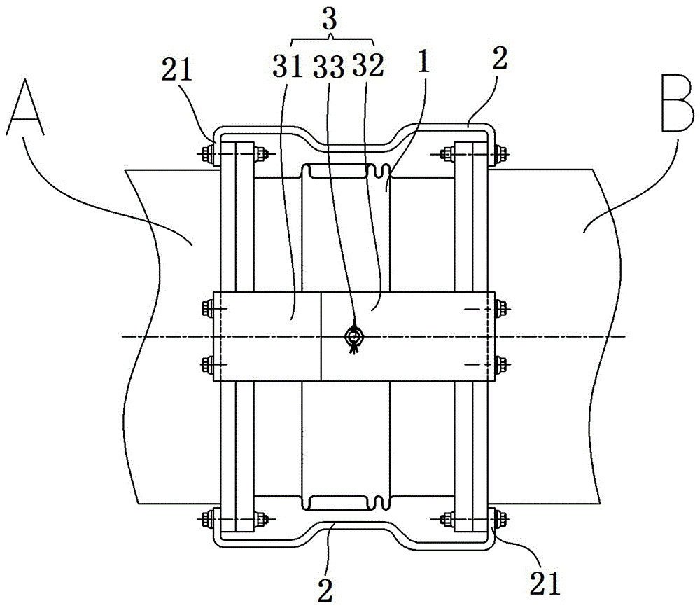
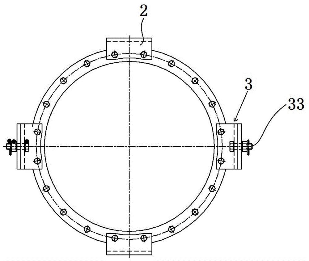
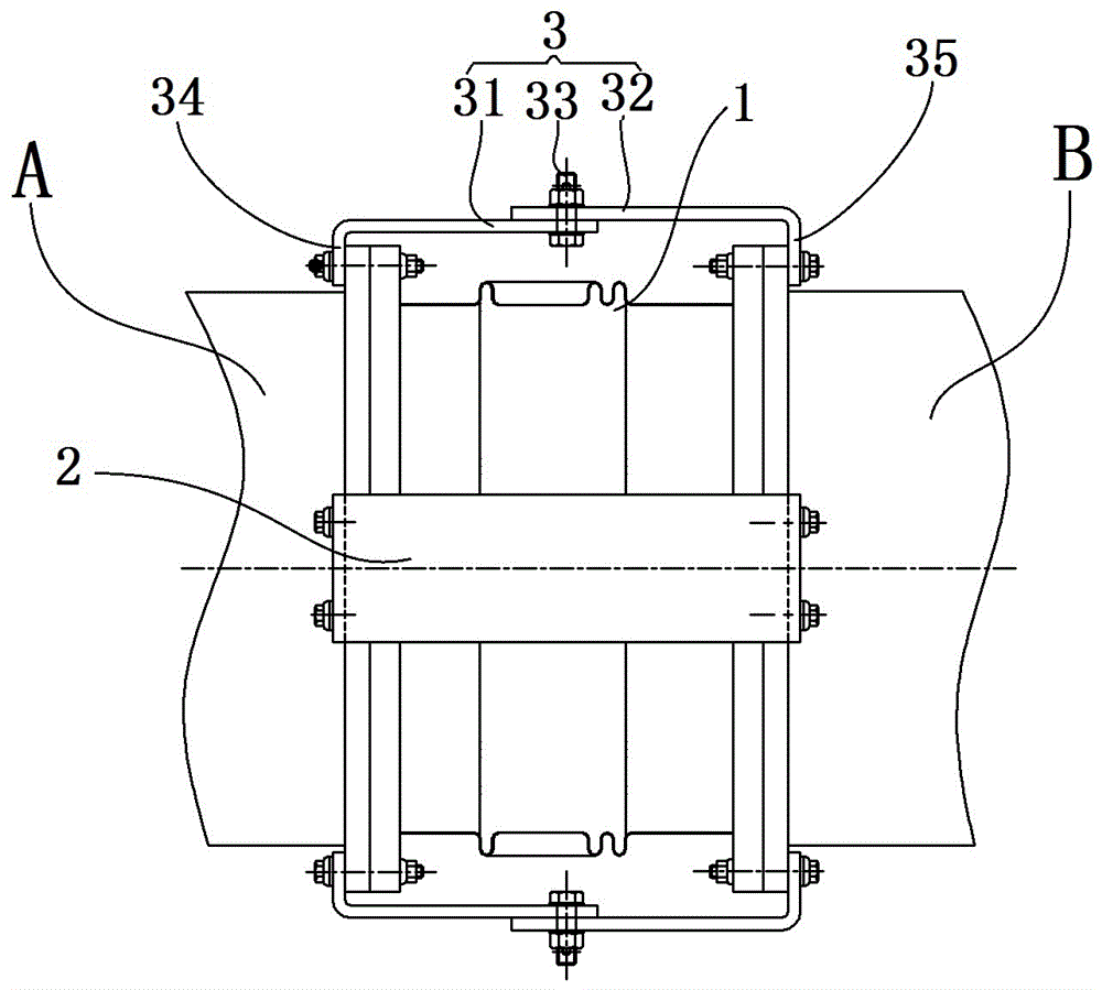
[0017] Specific embodiments of the busbar assembly of the present invention, such as Figure 1 to Figure 3 As shown, the busbar assembly includes the front section busbar A, the rear section busbar B and the busbar connection structure connecting the front section busbar A and the rear section busbar B. The busbar connection structure includes bellows 1 connected to the front section busbar A and the rear section busbar B respectively. As well as a guide bar assembly conductively connecting the front bus A and the rear bus B, the guide bar assembly includes a first guide bar 3 and a first and second guide bar 2 . There are two first guide bars 3, which are arranged symmetrically on the left and right sides of the corrugated pipe 1, and there are also two second guide bars 2, which are symmetrically arranged on the upper and lower sides of the corrugated ...


PUM


Abstract

The invention relates to a busbar assembly and a busbar connecting structure. When the busbar assembly disclosed by the invention is used for being connected with GIS devices, a front-section busbar and a rear-section busbar are connected with two GIS devices respectively, the front-section busbar and the rear-section busbar are connected with a corrugated pipe between the front-section busbar and the rear-section busbar through a busbar connecting structure, when the two GIS devices generate mismatching in the vertical direction, the corrugated pipe between the front-section busbar and the rear-section busbar is deformed by stress, the busbars are prevented from being damaged by stress to guarantee the flow capacity of shells of the busbars, a flow guide row set is arranged between the front-section busbar and the rear-section busbar through electric conduction connection, and the front section and the rear section of a first flow guide row in the flow guide row set are articulated and connected through an articulated shaft of which an axis is vertical to the extension direction of the corrugated pipe, so that the front section and the rear section of the first flow guide row can rotate relatively so as to adapt the mismatching in the vertical direction, or the front section and the rear section of the first flow guide row are articulated and connected through a universal hinge, so that the first flow guide row can adapt deformation in various directions.

Description

technical field [0001] The invention relates to a busbar assembly and a busbar connection structure. Background technique [0002] Gas-insulated metal-enclosed switchgear (hereinafter referred to as GIS) has been recognized by more and more users due to its small footprint, strong environmental adaptability, maintenance-free or less maintenance, etc. GIS devices are connected through busbars. In actual use, GIS equipment will be dislocated in the vertical direction due to the error of the civil foundation or the settlement of the civil foundation, especially when the GIS equipment is on different foundation slabs, it is more likely to cause vertical dislocation . When there is a vertical dislocation between GIS equipment, the busbar between the equipment will be subject to huge stress, which will easily cause damage to the busbar and seriously affect the safe operation of the power grid. Contents of the invention [0003] The object of the present invention is to provid...

Claims


Application Information

Patent Timeline
Patent Type & Authority Applications(China)
IPC IPC(8): H02B1/20H02G5/00
CPCH02B1/20H02G5/00
Inventor 董军利方煜瑛赵芳芳李健卢鹏许罗生王宝刚程尧轩张锐张建周清格乐吐张祎常克歌
Owner HENAN PINGGAO ELECTRIC
Why Eureka
Try Eureka