
a cooking device

A cooking device, the first-time technology, applied in the field of food processing equipment and cooking devices, can solve the problems of fast water consumption, single function, and inability to guarantee, and achieve the effect of high degree of control automation, safe and reliable principle, and simple main structure

Inactive Publication Date: 2018-11-06
QINGDAO UNIV
View PDF6 Cites 0 Cited by
  • Summary
  • Abstract
  • Description
  • Claims
  • Application Information

AI Technical Summary

Problems solved by technology

Equipment with simple structure and single function will be gradually replaced by highly intelligent equipment
At present, under the existing technical conditions, the cooking device used in the food processing industry and daily life has a simple structure and a single function. , which is extremely dangerous to the surrounding environment and damages the cooking device. For example, the stainless steel pot used to heat rice at home is widely used in the family. This kind of pot heats up quickly when used, and consumes water in the pot quickly. There will be a phenomenon of burning the pot or even burning the pot; or a cooking device with automatic power off. After the water is boiled dry, the user does not know, and waits for a long time before discovering that the power has been cut off and needs to be restarted. Opening the cooking device wastes a lot of time for the user, and also shortens the service life of the cooking device. For example, the heating lunch box disclosed in Chinese patent 2012104088737 is widely used in many people who go to work and travel, although the heating lunch box can be set to a regular time. , but the function is single, and it cannot ensure that the user can not only ensure that the food is heated thoroughly but also ensure safety when using it; The way of relying on steam alarm is non-intelligent, and it will bring danger to people around the cooking device

Method used


Image

  • a cooking device
  • a cooking device

Examples


Embodiment

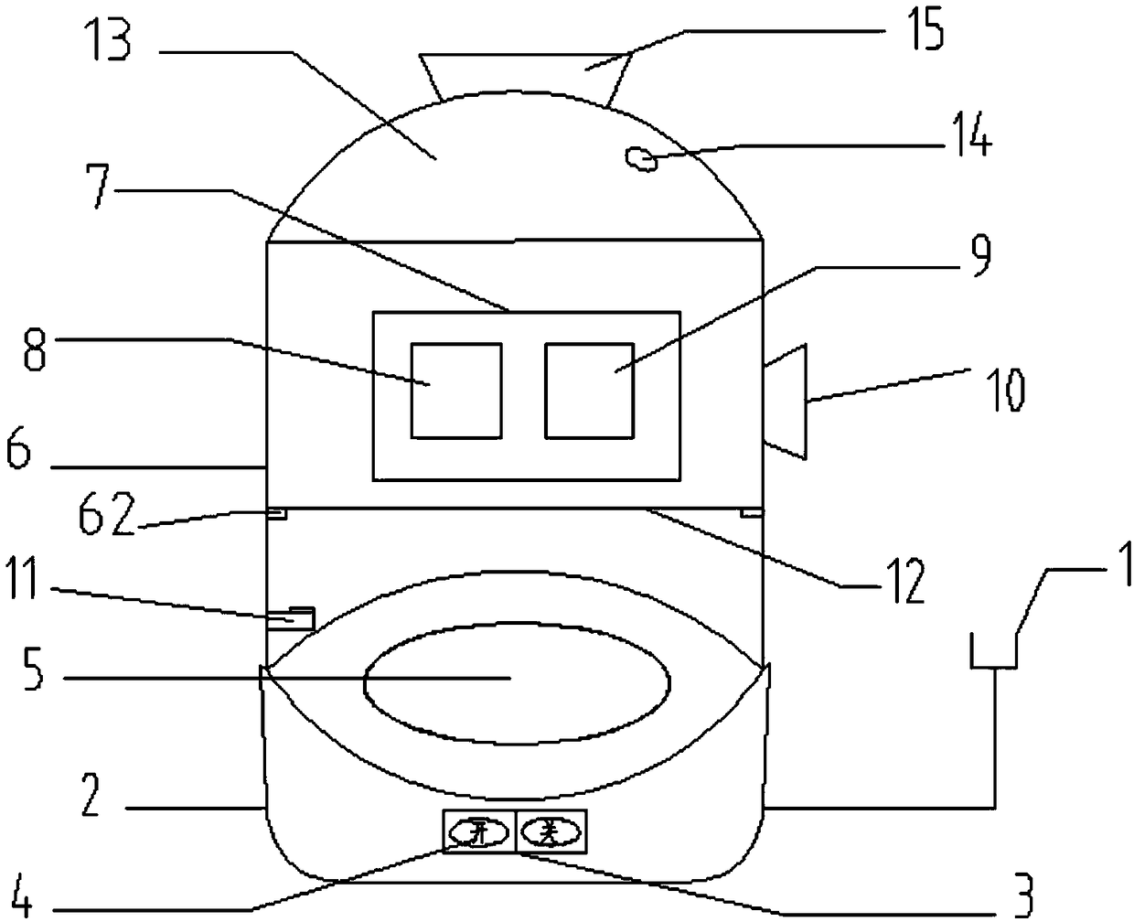
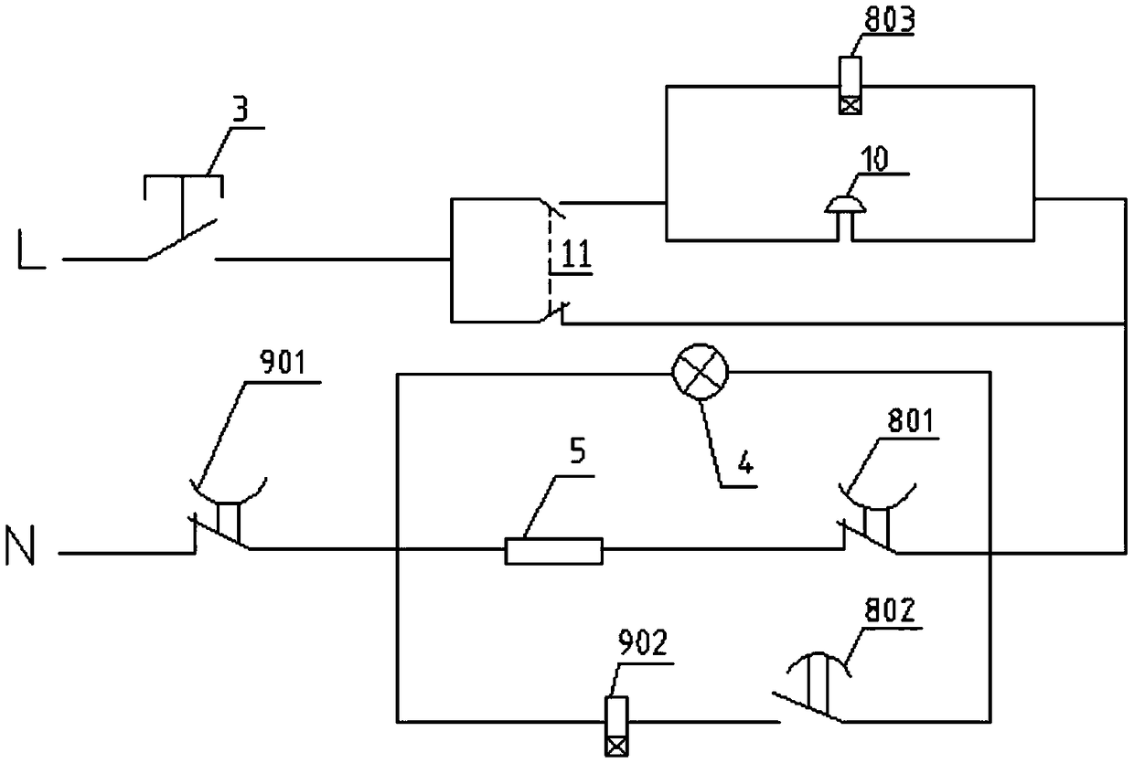
[0013] The main structure of this embodiment includes: power plug 1, base 2, power switch 3, power indicator light 4, heating plate 5, side wall 6, protective shell 7, first time relay 8, second time relay 9, buzzer device 10, liquid level sensor 11, spacer 12, upper cover 13, steam hole 14 and handle 15, the power plug 1 passes through the base 2 and is connected to the power switch 3 installed on the outer surface of the base 2, and the power indicator The lamp 4 is fixed in the base 2, and the light can be seen through the base 2 when the power indicator light 4 is on; the heating plate 5 is fixed inside the base 2, the side wall 6 is located on the base 2, and the bottom of the side wall 6 Equipped with a liquid level sensor 11, there is a 5% margin of liquid under the liquid level sensor 11 to prevent the heating plate 5 from burning the liquid level sensor 11, and the side wall 6 is respectively equipped with a first time relay 8 and a second time relay 9 And buzzer 10, ...


PUM


Abstract

The invention belongs to the technical field of electrical equipment and relates to a cooking device. The main structure of the cooking device comprises a power plug, a power switch, a power indicator lamp, a heating plate, a first time relay, a second time relay, a buzzer, a liquid level sensor and the like. In the using process, the cooking device is powered on, and the heating plate starts heating; when the liquid level in the cooking device is lower than the position of the liquid level sensor, the buzzer starts alarming, and the first time relay starts timing; if nobody conducts operation when set time is up, a delay opening contact of the first time relay is automatically switched off, meanwhile, a delay closing contact of the first time relay is switched on, and the second time relay starts timing; if still nobody conducts operation when set time is up, a delay opening contact of the second time relay is automatically switched off, and the device enables a whole circuit to be switched off. The cooking device is simple in main structure, safe and reliable in principle, flexible in use, high in control automation degree and environmentally friendly, saves energy and reduces consumption.

Description

Technical field: [0001] The invention belongs to the technical field of electrical equipment, and relates to food processing equipment, in particular to a cooking device. Background technique: [0002] With the advancement of technology, the use of equipment is becoming more and more intelligent. Equipment with simple structure and single function will be gradually replaced by highly intelligent equipment. At present, under the existing technical conditions, the cooking device used in the food processing industry and daily life has a simple structure and a single function. , which is extremely dangerous to the surrounding environment and damages the cooking device. For example, the stainless steel pot used to heat rice at home is widely used in the family. This kind of pot heats up quickly when used, and consumes water in the pot quickly. There will be a phenomenon of burning the pot or even burning the pot; or a cooking device with automatic power off. After the water is ...

Claims


Application Information

Patent Timeline
Patent Type & Authority Patents(China)
IPC IPC(8): A47J27/00A47J27/04A47J36/32
CPCA47J27/002A47J27/004A47J27/04A47J36/32A47J2027/043A47J2203/00
Inventor 于正河于希萌乔征马文静韩晨蔡冬
Owner QINGDAO UNIV
Learn More