Human bionic knee joint and hip joint transmission system

A transmission system and knee joint technology, applied in the field of human bionics and human-machine interface, can solve the problems of bulky, insufficient safety performance, large transmission wear, etc., to achieve reduced outline size, high motion transmission efficiency, and ensure safety Effect

Active Publication Date: 2018-12-11
TSINGHUA UNIV
View PDF6 Cites 0 Cited by
  • Summary
  • Abstract
  • Description
  • Claims
  • Application Information

AI Technical Summary

Problems solved by technology

[0005] Most of the current joint transmission designs are not very ideal, or there is a lack of transmission performance, or insufficient safety performance
Some existing joint transmission devices adopt bevel gear transmission or worm gear transmission, the transmission wears a lot, the efficiency is low, and the volume of this type of transmission device is very bloated; The cable unit is often exposed, and there is a risk of getting clothes or even fingers into the device; in addition, some designs try to simplify the transmission unit, and arrange the motor, transmission mechanism and joint shaft in series. The transmission efficiency of this arrangement is The loss is slightly small, but the projection width of the entire mechanism on the coronal plane of the human body will be very considerable, hindering the movement of the human body

Method used


Image

  • Human bionic knee joint and hip joint transmission system
  • Human bionic knee joint and hip joint transmission system
  • Human bionic knee joint and hip joint transmission system

Examples


Embodiment Construction

[0032] Embodiments of the present invention are described in detail below, examples of which are shown in the drawings, wherein the same or similar reference numerals designate the same or similar elements or elements having the same or similar functions throughout. The embodiments described below by referring to the figures are exemplary and are intended to explain the present invention and should not be construed as limiting the present invention.

[0033] The human bionic knee joint transmission system and the human bionic hip joint transmission system proposed by the present invention are further described in detail below in conjunction with the accompanying drawings and embodiments:

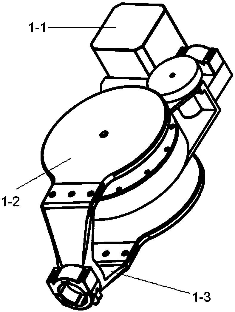
[0034] figure 1 It is a structural schematic diagram of a human bionic knee joint transmission system according to an embodiment of the present invention, including a transmission unit 1-2, a power unit 1-1 fixed on the top and a bottom of the transmission unit, a motion output unit 1-3, and...


PUM


Abstract

A bionic knee joint transmission system and a bionic hip joint transmission system of a human body disclosed by the invention belong to the technical field of human body simulation and man-machine interfaces. Each system comprises a power unit, a transmission unit and a motion output unit, wherein the transmission unit comprises an input module and an output module. In the knee joint transmission system, the power unit and the motion output unit are located on the top and the bottom of the transmission unit respectively. In the hip joint transmission system, the power unit and the motion output unit are located inside the transmission unit. Tops and bottoms of the two joint transmission systems are equipped with interfaces which are connected to other bionic structural parts of the human body respectively; the input and output modules of the transmission units of the two joint transmission systems are connected to the corresponding power units and motion output units respectively; and the transmission units transform high-speed rotation input by the power units into low-speed rotation which satisfies knee joints and hip joints of the human body on human body vertical planes, and the motion output units transmit the low-speed rotation to the other bionic structural parts of the human body. The systems disclosed by the invention are matched with the other bionic structural parts of the human body, can ensure safety and have high motion transmission efficiency.

Description

technical field [0001] The invention belongs to the technical field of human body bionics and man-machine interface, and in particular relates to the design of human body bionic knee joint and hip joint motion devices. Background technique [0002] It has gradually become a hot topic in medical research in modern society to allow disabled and paraplegic patients to regain mobility. The emergence of exoskeletons for assisting people with lower limb disabilities to walk has solved this problem. [0003] The common configuration of the exoskeleton mechanism is to build a mechanism in parallel on both sides of the lower limbs of the human body and connect with the lower limbs of the human body. Or the same as the human body; a transmission device can be added to the joint device to support the human body while also assisting the movement of the lower limbs of the human body, between the hip joint device and the knee joint device of the leg mechanism on the same side, as well as...

Claims


Application Information

Patent Timeline
Patent Type & Authority Patents(China)
IPC IPC(8): A61H3/00
CPCA61H3/00A61H2201/1207A61H2201/1481A61H2201/1659A61H2205/088A61H2205/102
Inventor 施炯明包佳立张必聪胡佳音边正梁郑钢铁
Owner TSINGHUA UNIV
Why Eureka
Try Eureka