A building suspended ceiling installation structure and construction method thereof

A technology for installing structures and suspended ceilings, which is applied to building components, building structures, buildings, etc., can solve problems such as complex structures, and achieve the effects of simple installation process, convenient height adjustment, labor-saving, and strong practicability

Active Publication Date: 2021-03-19
韶关市住宅建筑工程有限公司
View PDF9 Cites 0 Cited by
  • Summary
  • Abstract
  • Description
  • Claims
  • Application Information

AI Technical Summary

Problems solved by technology

The technical problem of this snap-tooth keel ceiling structure is that the structure is complicated, and the existence of the suspender 81 and the main keel 83 lengthens the distance between the gusset 4 and the ceiling, so this kind of ceiling structure is generally only suitable for buildings with a higher floor height. room, because the length of the light suspender is only 20 cm to 30 cm, for the existing ordinary houses, the general floor height is only 2.9 meters, it is obviously inappropriate to adopt this kind of ceiling structure, but the function of the suspender 81 is to connect With height adjustment, because the boom 81 acts as an adjustment function, it cannot be omitted, because the ceiling may be uneven, and the height of the keel needs to be adjusted

Method used


Image

  • A building suspended ceiling installation structure and construction method thereof
  • A building suspended ceiling installation structure and construction method thereof
  • A building suspended ceiling installation structure and construction method thereof

Examples


Embodiment 1

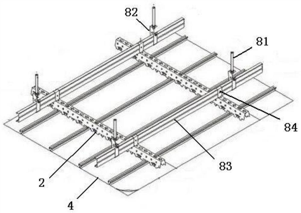
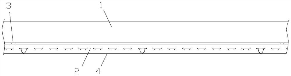
[0064] Such as figure 2 , 4 As shown, the building ceiling installation structure described in this embodiment includes several snap-tooth keels 2 connected to the ceiling 1 through wall connectors 3. The snap-tooth keels 2 are composed of a top surface and two front and rear sides. A connecting hole 21 that matches the wall connector 3 is provided on the top surface of the snap-tooth keel 2, and a slot 22 is arranged at intervals at the bottom of the side of the snap-tooth keel 2, and a buckle is snapped on the snap-tooth keel 22. Plate 4, characterized in that:

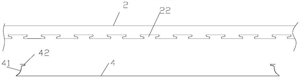
[0065] Such as image 3 As shown, upper flanges 41 are provided on both sides of the gusset plate 4, and the top of the upper flange 41 has a snap-in portion 42 that can be snapped into the card slot 22, and the snap-in portions of two adjacent gusset plates 4 42 is snapped into the same slot 22 in a mirror image; it should be noted that: the snap-tooth keel 2 and the pinch plate 4 can also be other matching str...

Embodiment 2

[0088] This embodiment describes the construction method of the building ceiling installation structure described in Embodiment 1, which includes the steps of installing the snap-tooth keel 2 on the ceiling 1 and the step of clamping the buckle plate 4 on the snap-tooth keel 2, which It is characterized in that the step of installing the bayonet keel 2 on the ceiling 1 includes the following steps:

[0089]Drill some rows of mounting holes 11 on the ceiling 1;

[0090] Install the wall connector 3 in the installation hole 11: insert the core rod 6 into the expansion tube 5, knock the expansion tube 5 into each installation hole 11, twist the threaded ring 63 to expand the expansion foot 53, and insert the expansion tube 5 and the core rod 6 are firmly fixed on the ceiling 1, and then the lifting insertion tube 70 of the lifting assembly 7 is inserted into the first cylindrical cavity 64 of the core rod 6, and the beads 707 are positioned in the arc groove 66 during insertion; ...

Embodiment 3

[0099] Such as Figure 13 As shown, the building ceiling installation structure described in this embodiment is different from Embodiment 1 in that straight wall sections 56 are provided on both sides of the lower part of the lower pipe body 52 .

[0100] The straight wall sections 56 on both sides are convenient for the vise to clamp the lower pipe body 52 , and the straight wall sections 56 at least partly expose the bottom surface of the ceiling 1 during installation.


PUM


Abstract

The invention discloses a building suspended ceiling installation structure. The building suspended ceiling installation structure comprises a plurality of clamping-tooth keels connected to a ceiling through wall connecting pieces, wherein buckling boards are clamped on the clamping-tooth keels, and each wall connecting piece comprises an expansion pipe, a core rod and a lifting assembly. The expansion pipes are embedded into installing holes formed in the ceiling, and each lifting assembly comprises a lifting insertion pipe, a first movable part, a second movable part and a third movable part. The third movable part is composed of a limiting end head, a screw, a locking nut and a second convex lug, and the top surfaces of the clamping-tooth keels are limited between the limiting end heads and the locking nuts after locking through the locking nuts. The building suspended ceiling installation structure has the advantages that the wall connecting pieces are embedded into the ceiling, so that the distances between the ceiling and the buckling boards are obviously shortened, and especially hanging rods and main keels are omitted compared with the prior art. In addition, the wall connecting pieces have height adjusting and tensioning functions, so that the building suspended ceiling installation structure is firm and is suitable for existing domestic residences. The invention further discloses a construction method of the building suspended ceiling installation structure.

Description

technical field [0001] The invention relates to a building decoration structure, in particular to a building suspended ceiling installation structure. Background technique [0002] Existing building ceilings generally adopt suspended ceilings to make them more beautiful or to achieve corresponding functions. [0003] figure 1 Shown is an existing suspended ceiling structure, which adopts snap-tooth keel 2 to install buckle plate 4, which mainly includes boom 81, main keel hanger 82, main keel 83, snap-tooth keel hanger 84, clip Teeth keel 2 and buckle plate 4; the top of the boom 81 is connected to the expansion screw installed on the ceiling through the connecting piece, the boom 81 is connected to the main keel 83 through the main keel hanger 82, and the snap-tooth keel 2 is hung by the snap-tooth keel Part 84 is connected on the main keel 2, and the buckle plate 4 is clamped on the bayonet keel 2. The technical problem of this snap-tooth keel ceiling structure is that ...

Claims


Application Information

Patent Timeline
Patent Type & Authority Patents(China)
IPC IPC(8): E04B9/06E04B9/28E04B9/30
CPCE04B9/06E04B9/28E04B9/30
Inventor 陈孔杰
Owner 韶关市住宅建筑工程有限公司
Why Eureka
Try Eureka