A kind of production method of gas lift and liquid discharge with self-buffered plunger

A production method and plunger technology, which are applied to parts of pumping devices for elastic fluids, earthwork drilling, liquid fuel engines, etc., can solve problems such as pollution, heavy workload, and high cost

Active Publication Date: 2018-08-14
PETROCHINA CO LTD
View PDF7 Cites 0 Cited by
  • Summary
  • Abstract
  • Description
  • Claims
  • Application Information

AI Technical Summary

Problems solved by technology

[0004] The purpose of the present invention is to solve the problems that the existing foam drainage process for horizontal wells has the disadvantages of pollution, high cost, heavy workload, and poor drainage effect

Method used


Image

  • A kind of production method of gas lift and liquid discharge with self-buffered plunger

Examples


Embodiment 1

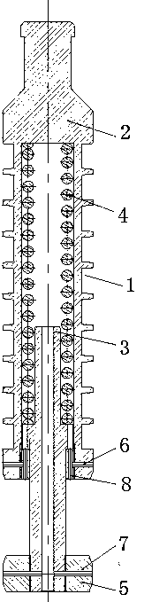
[0019] In order to solve the disadvantages of pollution, high cost, heavy workload, and poor drainage effect caused by the foam drainage process of traditional horizontal wells, this embodiment provides such problems as figure 1 A plunger with its own buffer is shown, including a plunger body 1 and a guide rod 3, the plunger body 1 is a hollow cavity, a buffer spring 4 is arranged in the hollow cavity, and one end of the guide rod 3 extends into the hollow cavity , the other end stretches out of the plunger body 1 and is covered with a guide head 5, the top of the plunger body 1 is a plunger fishing head 2; the guide rod 3 is covered with a retaining ring 8, which is located on the column The bottom end of the inner wall of the plug body 1, the retaining ring 8 and the plunger body 1 are connected by a spring pin-6.

[0020] The course of work of this plunger provided by the present embodiment is:

[0021] In the shut-in state, the plunger with its own buffer is lowered into ...

Embodiment 2

[0025] On the basis of Embodiment 1, in order to reduce the weight of the entire plunger and discharge the sand contained in the bottom hole fluid, the guide rod 3 has a hollow structure. In order to fix the position of the buffer spring 4 and prevent the buffer spring 4 from slipping, a step is provided at one end of the guide rod 3 extending into the hollow cavity of the plunger body 1 . Between described guide head 5 and guide rod 3, connect by spring cylindrical pin 2 7 or screw thread, spring cylindrical pin 2 7 plays the effect of fixing guide head 5. In order to realize that the plunger body 1 can go down under its own weight and finally stop running under the well shut-in state, the outer diameters of the plunger body 1 and the guide head 5 are both larger than the inner diameter of the tubing in the horizontal section of the horizontal well. In order to make the plunger body 1 fall smoothly, the guide head 5 is screwed to the bottom end of the guide rod 3, and the gui...

Embodiment 3

[0027] This embodiment provides a gas-lift liquid drainage production method with a self-buffered plunger. In the well shut-in state, the self-buffered plunger is lowered into a horizontal well (or a highly deviated well or a vertical well), and the The plunger with buffer moves downward as a whole and reaches the position of the reducing joint of the horizontal well. The guide head 5 of the plunger stops moving when encountering resistance, the plunger body 1 continues to descend under the action of inertia, the buffer spring 4 is compressed, and the plunger body 1 stops descending Then the well is opened, the plunger moves upward under the action of formation gas or injected gas, and at the same time lifts the bottom hole liquid to the well head, so far completes a cycle of gas lift liquid drainage and starts the next cycle. Safely realize gas recovery with plunger gas lift and liquid drainage with built-in buffer in horizontal gas wells. This device has been successfully pu...


PUM


Abstract

The invention provides a self-buffering plunger. A spring is arranged in the plunger, which can achieve a self-buffering function of the plunger and can replace the conventional downhole buffers; a bottom guide rod and a baffle ring can fix a position of the spring, prevent the spring from sliding and falling off, and can support the spring; a guide head plays a role in guiding in falling of the plunger and can support the plunger body in a well bottom, and the guide rod is of a hollow structure; spring cylindrical pins can fix the baffle ring and the guide head. The plunger is mainly used for highly-deviated wells and horizontal wells, can overcome the problem that the conventional horizontal wells cause pollution, are high in cost, are large in workload, and are poor in fluid flowing effect due to the foam water drainage technology, can achieve the fact that horizontal gas wells can perform fluid flowing and gas production by using the plunger gas lift technology, can solve the difficult problem of fluid flowing and gas production of more than 1200 horizontal gas wells in a Changqing gas field, and can be used for the highly-deviated wells and vertical shafts, and can simplify downhole tools.

Description

technical field [0001] The invention belongs to the technical field of gas production in gas fields, and in particular relates to a production method for gas-lift liquid drainage with a plunger with a buffer. Background technique [0002] The plunger gas lift process is to use the energy of the gas well itself to discharge the liquid out of the wellbore. The plunger acts as a mechanical interface between the gas and the liquid to prevent the gas from going up and the liquid from falling back, reducing the liquid slippage effect and increasing the intermittent lifting efficiency. Plunger gas lift is a simple and efficient method of liquid drainage and gas recovery. It is a special form of intermittent gas lift. The plunger, as a solid sealing interface, separates the lifted gas from the lifted liquid, reducing gas Channeling and liquid fallback increases the efficiency of lifting gas. The energy of the plunger gas lift mainly comes from the formation, but when the energy of ...

Claims


Application Information

Patent Timeline
Patent Type & Authority Patents(China)
IPC IPC(8): F04B53/14E21B43/00
CPCE21B43/122F04B53/14
Inventor 韩强辉田伟杨亚聪吕伟
Owner PETROCHINA CO LTD
Why Eureka
Try Eureka