Plunger gas-lifting draining device used for horizontal gas well and production method

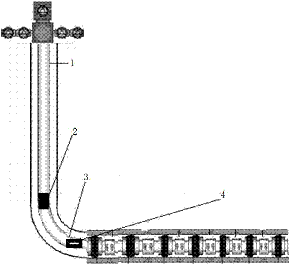
A liquid drainage device and plunger technology, which is applied in drilling equipment, earthmoving, wellbore/well components, etc., can solve the problem that it is impossible to realize the lifting of liquid accumulation in the whole wellbore of horizontal wells, and it is difficult for downhole tools to enter the highly deviated well section. , affecting the efficiency of plunger gas lift liquid discharge and other problems, to achieve the effect of simplifying downhole tools, simple structure, and increasing the running depth

Inactive Publication Date: 2018-01-05
PETROCHINA CO LTD
View PDF5 Cites 4 Cited by
  • Summary
  • Abstract
  • Description
  • Claims
  • Application Information

AI Technical Summary

Problems solved by technology

Since the horizontal well deviates gradually from the kick-off point to the window entry point at the bottom of the well, the existing downhole tools are difficult to enter the highly deviated well section, and cannot be locked in the highly deviated well section, so they can only be used in vertical wells part
Moreover, the tubing of most horizontal wells in the Changqing gas area will shrink in diameter before

Method used


Image

  • Plunger gas-lifting draining device used for horizontal gas well and production method
  • Plunger gas-lifting draining device used for horizontal gas well and production method
  • Plunger gas-lifting draining device used for horizontal gas well and production method

Examples


Example Embodiment

[0029] In the description of the present invention, it should be understood that the orientation or positional relationship indicated by the terms "upper", "lower", "inner", "outer", etc. are based on the orientation or positional relationship shown in the drawings, and are only for It is convenient to describe the present invention and simplify the description, instead of indicating or implying that the device or element referred to must have a specific orientation, be constructed and operated in a specific orientation, and therefore cannot be understood as a limitation to the present invention. In addition, the terms "first" and "second" are only used for descriptive purposes, and cannot be understood as indicating or implying relative importance or implicitly indicating the number of indicated technical features. Thus, the features defined with "first" and "second" may explicitly or implicitly include one or more of these features. In the description of the present invention...


PUM


Abstract

The invention discloses a plunger gas-lifting draining device used for a horizontal gas well and a production method. The device comprises a self-buffering plunger and a uniflow device which are arranged in an oil pipe, the oil pump comprises two sections of pipelines who have different pipe diameters and are connected by a reducing short section, the self-buffering plunger is arranged in the part, which is located at the upper part of the reducing short section, of the pipeline, the uniflow device is used for controlling a gas liquid to flow unidirectionally from bottom to top and arranged inthe part, located at the lower part of the reducing short section, of the pipeline, the shaft accumulated fluid can be lifted to the upper part of the uniflow device by the own energy of the gas well, is delayed, and is lifted to the well mouth by the aid of the self-buffering plunger, and drainage production is completed. A downhole tool of an existing plunger device is simplified; the functionof gas liquid unidirectional flow is realized by the uniflow device, the structure is simple and easy to put and slave, the own lifting capacity of the gas well is effectively utilized, the shaft accumulated fluids of the horizontal gas well bottom part inclined shaft part and horizontal section are lifted, the shaft liquid column height is reduced greatly, the gas yield is increased, and the horizontal gas well draining gas production difficulty is effectively solved.

Description

technical field [0001] The invention belongs to the technical field of gas production in gas fields, and in particular relates to a plunger gas-lift liquid drainage device and a production method for horizontal gas wells. Background technique [0002] There are currently more than 1,300 horizontal gas wells in the Changqing gas area of ​​the Ordos Basin, and it is estimated that the number will reach 2,700 in 10 years. Gas wells with gas production below 20,000 m3 / d will account for 76.7%, and the problem of liquid accumulation is gradually emerging. [0003] The plunger gas lift liquid drainage technology uses the plunger as the gas-liquid separation interface, which can effectively prevent the gas from moving up and the liquid from slipping, and increase the efficiency of liquid lifting. In addition, this technology does not require chemical agents and is environmentally friendly. Foreign countries believe that the plunger gas lift technology is the most economical and eff...

Claims


Application Information

Patent Timeline
IPC IPC(8): E21B43/12E21B17/00
Inventor 韩强辉李耀德田伟刘双全杨亚聪白晓弘卫亚明李辰李丽
Owner PETROCHINA CO LTD
Why Eureka
Try Eureka