
Ball valve and fluid pipe network

A valve body and ball valve technology, applied in the field of fluid control equipment, can solve the problems of valve core and valve seat damaged parts, valve seal failure, etc., and achieve the effect of reducing maintenance times, improving safety, and reducing fluid leakage

Active Publication Date: 2020-06-05
湖南西爱斯流体控制设备有限公司
View PDF6 Cites 0 Cited by
  • Summary
  • Abstract
  • Description
  • Claims
  • Application Information

AI Technical Summary

Problems solved by technology

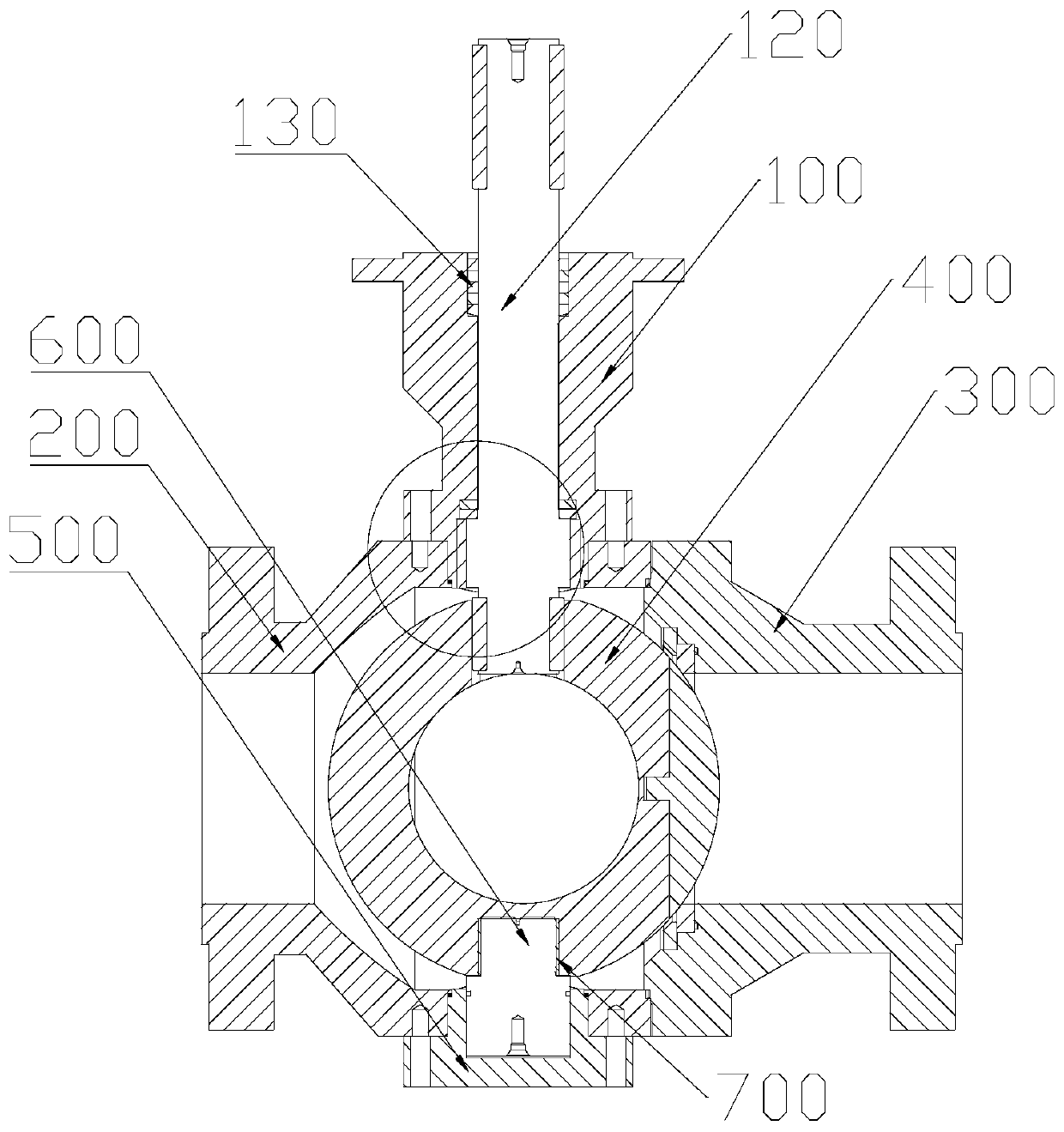
[0005] The purpose of the present invention is to provide a ball valve and a fluid pipe network to solve the technical problem in the prior art that the friction between the valve core and the valve seat causes damage to the parts, which eventually leads to the sealing failure of the valve.

Method used


Image

  • Ball valve and fluid pipe network
  • Ball valve and fluid pipe network
  • Ball valve and fluid pipe network

Examples


Embodiment Construction

[0029] The technical solutions of the present invention will be clearly and completely described below in conjunction with the accompanying drawings. Apparently, the described embodiments are some of the embodiments of the present invention, but not all of them. Based on the embodiments of the present invention, all other embodiments obtained by persons of ordinary skill in the art without making creative efforts belong to the protection scope of the present invention.

[0030] In the description of the present invention, it should be noted that the terms "center", "upper", "lower", "left", "right", "vertical", "horizontal", "inner", "outer" etc. The indicated orientation or positional relationship is based on the orientation or positional relationship shown in the drawings, and is only for the convenience of describing the present invention and simplifying the description, rather than indicating or implying that the referred device or element must have a specific orientation, ...


PUM


Abstract

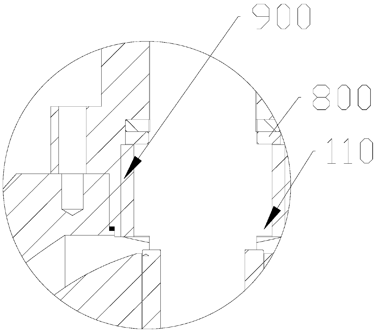
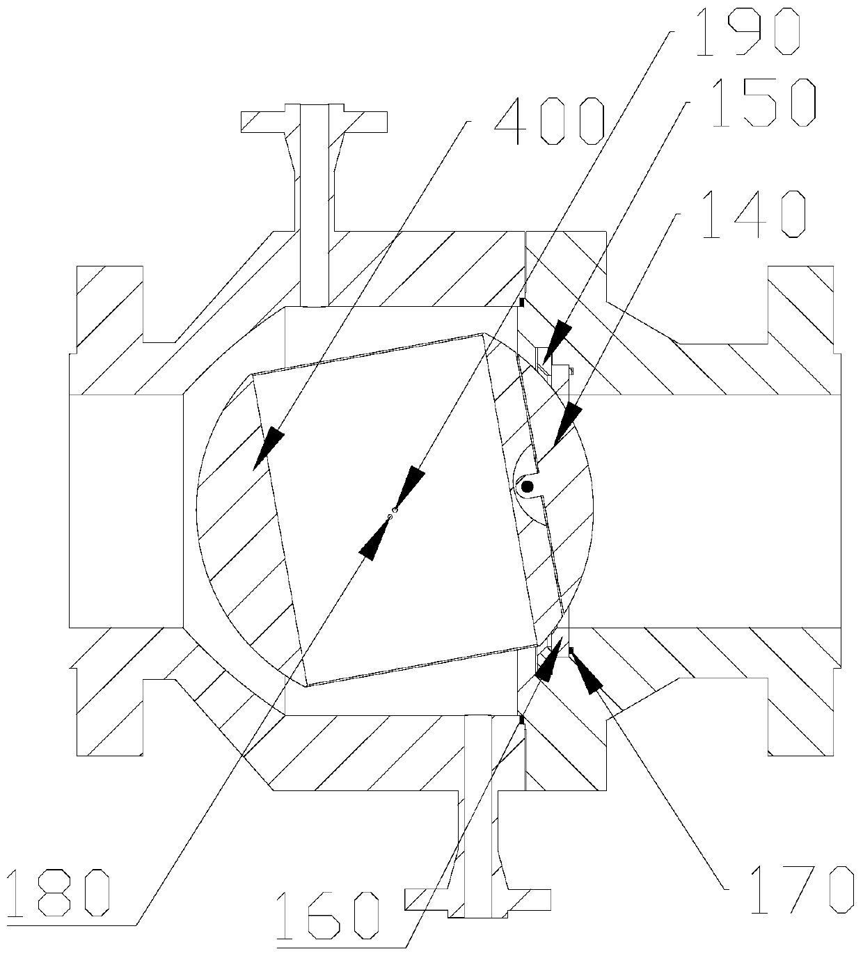
The invention provides a ball valve and a fluid pipe network, and relates to the technical field of fluid control equipment. The ball valve comprises a stuffing box, an upper valve body, a lower valve body and a bottom cap; a containing cavity used for containing a valve element is formed by the upper valve body and the lower valve body; the bottom cap is arranged at the lower end of the lower valve body and used for fixing the lower valve body and a support shaft in a sealing mode; the stuffing box is arranged at the upper end of the lower valve body and used for fixing the lower valve body and a rotation shaft in a sealing mode; a through hole is formed in the stuffing box, and the rotation shaft is connected with the valve element through the through hole; the valve element comprises a valve element body and a sealing plate; the sealing plate is provided with a connecting part; an installing groove is formed in the valve element body. According to the ball valve, when the valve element rotates, a valve base does not make contact with the valve element, friction is not generated between the valve element and the valve base, harmful friction is fundamentally eliminated, and the valve element and valve base damage problem generated by friction is solved.

Description

technical field [0001] The invention relates to the technical field of fluid control equipment, in particular to a ball valve and a fluid pipe network. Background technique [0002] The trunnion ball valve is one of the most widely used valves in industry. In the fixed ball valve, the ball has a rotating shaft and a supporting shaft, both of which are fixed on the valve body, the position of the ball is fixed, and the fluid pressure cannot make it move. There are valve seats on both sides of the ball, and the valve seat is pressed against the ball by means of the spring and the thrust of the fluid to establish a sealing specific pressure. [0003] The main function of this kind of valve is to cut off or connect the fluid channel in the pipeline, apply a certain torque on the shaft with the help of a handle or a driving device and transmit it to the ball to make it rotate 90 degrees, the through hole of the ball and the center of the channel of the valve body The lines are ...

Claims


Application Information

Patent Timeline
Patent Type & Authority Patents(China)
IPC IPC(8): F16K5/06F16K5/20F16K41/02
CPCF16K5/0605F16K5/0647F16K5/0694F16K5/20
Inventor 吴军
Owner 湖南西爱斯流体控制设备有限公司
Learn More