Gas leakage safety valve

A technology of gas leakage and safety valve, which is applied in the directions of safety valve, control valve, balance valve, etc., can solve the problems of uncompact structure and large overall gas safety valve, and achieve the effect of stable flow rate

Inactive Publication Date: 2017-03-15
玉环市中良流体智控股份有限公司
View PDF8 Cites 4 Cited by
  • Summary
  • Abstract
  • Description
  • Claims
  • Application Information

AI Technical Summary

Problems solved by technology

The valve ball is used to switch the valve in daily use, and the structure of the sealing block and the valve core rod is used to seal the valve body when gas leakage occurs in the pipeline. The structure of the core rod is set in the air intake passage, and the two are independent of each other. In order to install the structure of the valve ball, the sealing block and the valve core rod in the valve body, the valve body needs to be made larger to meet the installation requirements. As a result, the overall size of the gas safety valve is large and the structure is not compact

Method used


Image

  • Gas leakage safety valve
  • Gas leakage safety valve
  • Gas leakage safety valve

Examples


Embodiment 1

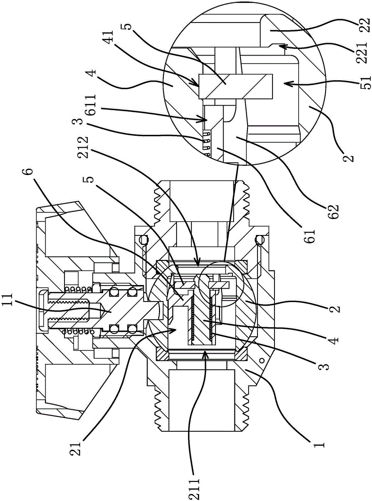
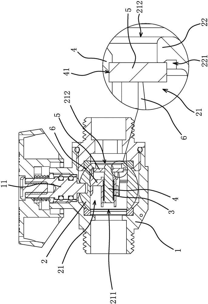
[0029] Such as Figure 1 to Figure 3As shown, the gas leakage safety valve includes a valve body 1, a valve ball 2 arranged in the valve body 1, and a valve stem 11 capable of driving the valve ball 2 to rotate. The valve ball 2 has a passage 21, and one end of the passage 21 is an air inlet. 211, the other end of the channel 21 is an air outlet 212; the safety valve also includes a spring 3, a check rod 4 and a circular sealing piece 5, and the check rod 4 has an annular groove 41, and the check rod 4 passes through The sealing sheet 5 and the sealing sheet 5 are stuck in the annular groove 41 .

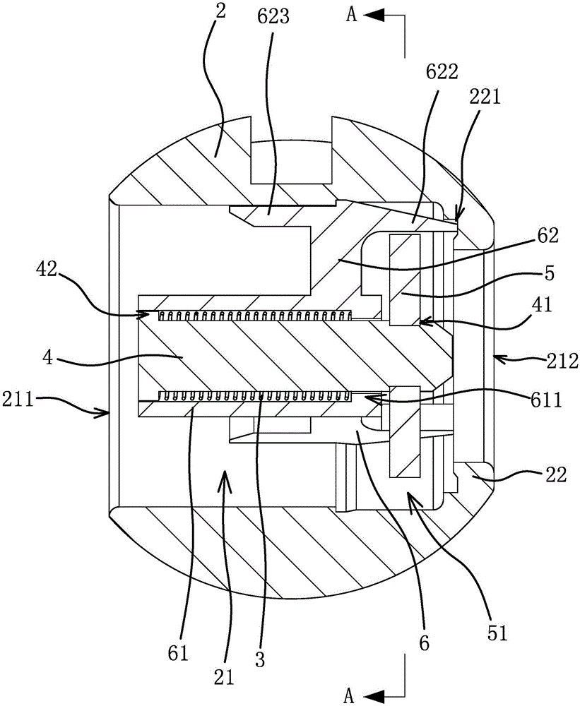
[0030] Such as Figure 1 to Figure 4 As shown, the valve ball 2 is fixed with a non-return support 6, the non-return rod 4 is pierced on the non-return support 6 and the non-return rod 4 is arranged along the extension direction of the channel 21, the sealing sheet 5 is located in the valve ball 2 and Close to the gas outlet 212, the spring 3 is arranged between the non-return rod...

Embodiment 2

[0035] The structure and principle of this embodiment are basically the same as those of Embodiment 1, except that: there is a section of sealing section inside the valve ball 2, and the diameter of the sealing section gradually decreases from the end close to the air inlet 211 to the end close to the air outlet 212. The diameter of the sealing section is smaller than the diameter of the sealing piece 5. When the gas is not leaking, the sealing piece 5 is located in the valve ball 2 on the side of the sealing section close to the air inlet 211. When the gas leaks, the sealing piece 5 can move into the sealing section and be in contact with it. The inner wall of the sealing section seals against. When the gas is not leaking, the sealing sheet 5 is located outside the sealing section, so the gas can pass through the sealing section through the gas gap 51, and when the gas leaks, the sealing sheet 5 can move into the sealing section and seal against the inner wall of the sealing s...


PUM


Abstract

The invention provides a gas leakage safety valve, belongs to the technical field of gas safety and solves the technical problems of incompact structure and the like of an existing gas leakage safety valve. The gas leakage safety valve comprises a valve body, a valve ball arranged in the valve body and a valve rod capable of driving the valve ball to rotate. The gas leakage safety valve further comprises a spring, a check rod and a sealing sheet fixed at one end of the check rod; a check support is fixed in the valve ball; the check rod is in sliding connection with the check support; the sealing sheet is positioned in the valve ball; the spring is arranged between the check rod and the check support; a gas through gap is formed between the sealing sheet and the valve ball under the action of the spring; when moving towards a gas outlet of the valve ball, the sealing sheet can be sealed with the valve ball. The gas leakage safety valve provided by the invention has the advantages that not only can the opening and the closing of gas be realized, but also the gas can be automatically blocked when gas leakage occurs; the structure is compact.

Description

technical field [0001] The invention belongs to the technical field of gas safety and relates to a gas leakage safety valve. Background technique [0002] During the use of gas, there will be pipeline leakage or sudden rupture. In order to ensure the safety of gas use, it is necessary to automatically block the pipeline when there is leakage or sudden rupture of the pipeline to avoid continuous leakage of gas. A gas safety valve is installed in the pipeline to achieve this. [0003] When the pipeline leaks or bursts suddenly, the gas flow in the pipeline will increase sharply. The existing gas safety valve mainly realizes blocking the pipeline according to the change of the gas flow in the pipeline. For example, the gas safety valve disclosed in the Chinese patent literature [authorized announcement number CN201363450Y] includes a valve body with an air inlet channel and an air outlet channel, and a valve stem is arranged in the valve body. One end of the valve stem is conn...

Claims


Application Information

Patent Timeline
IPC IPC(8): F16K15/18F16K17/04F16K17/168F16K5/06
CPCF16K5/0605F16K17/0413F16K17/168F16K15/1848
Inventor 蔡善良蒋祖法
Owner 玉环市中良流体智控股份有限公司
Why Eureka
Try Eureka