A phase-sensitive optical time domain reflectometer phase demodulation system and phase demodulation method

A technology of time domain reflectometer and phase sensitive light, applied in the direction of converting sensor output, using optical devices to transmit sensing components, measuring devices, etc., can solve the problems of being easily affected by the environment, difficult to implement, expensive, etc. Detection distance, good signal-to-noise ratio and stability, the effect of eliminating phase drift

Active Publication Date: 2018-08-28
中国电子科技集団公司第三十四研究所
View PDF10 Cites 0 Cited by
  • Summary
  • Abstract
  • Description
  • Claims
  • Application Information

AI Technical Summary

Problems solved by technology

The first two require the introduction of an interferometer structure, which is easily affected by the environment and thus introduces additional noise
Digital coherent demodulation requires a large amount of high-speed data reception and processing, so it is expensive and difficult to implement

Method used


Image

  • A phase-sensitive optical time domain reflectometer phase demodulation system and phase demodulation method
  • A phase-sensitive optical time domain reflectometer phase demodulation system and phase demodulation method
  • A phase-sensitive optical time domain reflectometer phase demodulation system and phase demodulation method

Examples


Embodiment 1

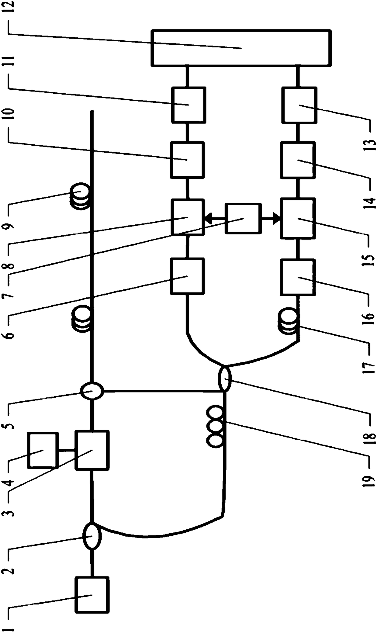
[0023] Example 1 of this phase-sensitive optical time domain reflectometer (φ-OTDR) phase demodulation system figure 1 As shown, the narrow linewidth laser 1 with the wavelength of C-band is connected to the fiber coupler 2, and the splitting ratio of the fiber coupler 2 is

[0024] 90:10. 90% of the light is connected to the acousto-optic modulator 3 as the sensing light, the signal driver 4 is connected to the acousto-optic modulator 3, the acousto-optic modulator 3 modulates the connected sensing light and shifts the frequency fc through the circulator 5 and sensor fiber 9 are connected.

[0025] The fiber coupler 2 connects 10% of the light as the reference light to the polarization controller 19, the output end of the polarization controller 19 is connected to one input end of the 2×2 fiber coupler 18, and the other end of the circulator 5 is connected to the 2×2 fiber The other input end of the coupler 18, the coupled light is divided into two beams of signal light, one of wh...

Embodiment 2

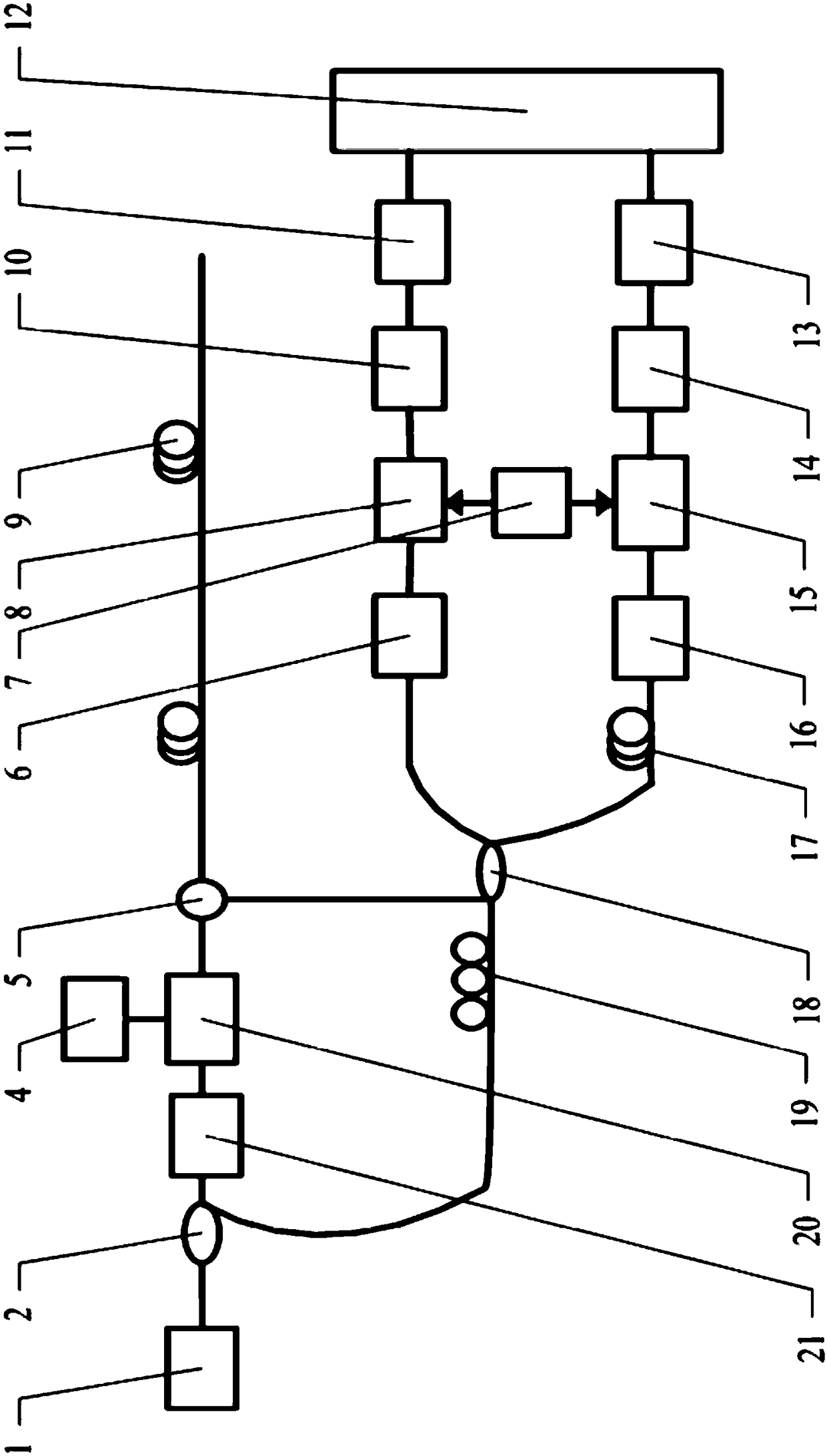
[0032] Example 2 of the phase demodulation system of the phase sensitive optical time domain reflectometer is as figure 2 As shown, the structure is similar to Embodiment 2 of the above-mentioned phase demodulation system, but the acousto-optic modulator 3 in Embodiment 1 is replaced by a frequency shifter 21 and an electro-optic modulator 20, and the signal driver 4 is connected to the electro-optic modulator 20, which is optically coupled 90% of the light split by the device 2 is connected to the frequency shifter 21 as the sensing light, the frequency shifter 21 is connected to the electro-optical modulator 20, and the electro-optical modulator 20 is connected to the circulator 5. Example 3 of Phase Demodulation System of Phase Sensitive Optical Time Domain Reflectometer

Embodiment 3

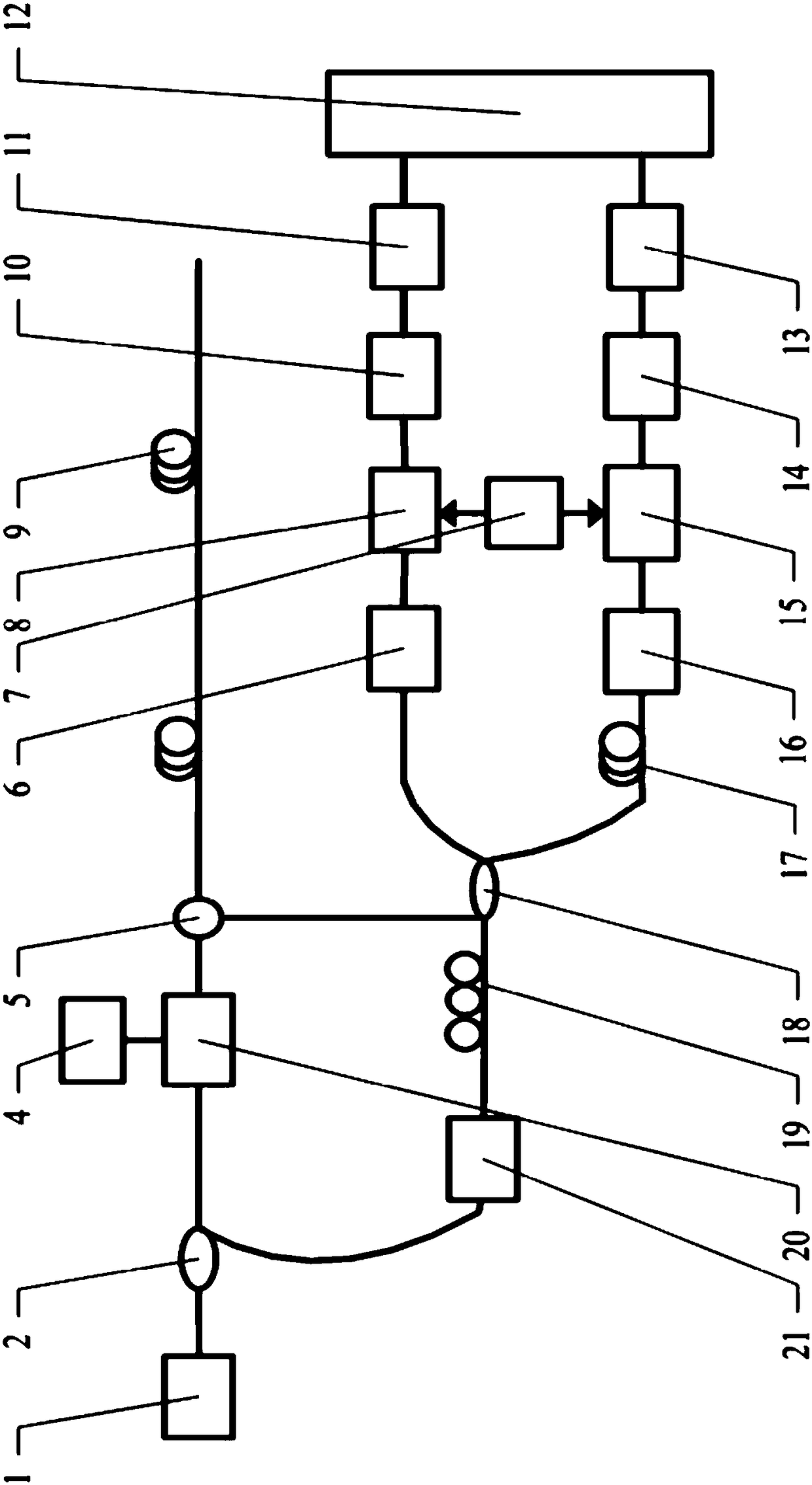
[0033] Example 3 of the phase demodulation system of the phase sensitive optical time domain reflectometer image 3 As shown, the structure is similar to Embodiment 1 of the above-mentioned phase demodulation system, but the acousto-optic modulator 3 in Embodiment 1 is replaced by an electro-optic modulator 20, and 90% of the light split by the fiber coupler 2 is connected to the electro-optic modulator 20 as sensing light. , Then connect the circulator 5; 10% of the light split by the fiber coupler 2 is connected to the frequency shifter 21 as the sensing light, and then connected to the polarization controller 19.

[0034] Phase demodulation method of phase-sensitive optical time domain reflectometer phase demodulation system embodiment 1

[0035] The first embodiment of the phase demodulation method is performed on the first embodiment of the above-mentioned phase-sensitive optical time domain reflectometer phase demodulation system.

[0036] The laser beam emitted by the narrow ...


PUM


Abstract

The invention discloses a phase demodulating system and a phase demodulating method for a phase sensitivity optical time-domain reflect meter. A narrow line-width laser is connected with an optical fiber coupler; a most part of sensation light is led into an acoustic optical modulator for modulation and frequency shift, and is subsequently led into a sensation optical fiber through a circulator; a small part of light is adopted as reference light which is led into a polarization controller, is led into a 2*2 optical fiber coupler together with the circulator, and is divided into two beams of signal light; one beam of the signal light is connected with an optical fiber time delay line; the two beams of the signal light are converted into electric signals through a photovoltaic conversion module; the electric signals are subjected to frequency mixing with fc signals through an electric frequency mixer, and are further led into a control center through a low pass filter and an analog-digit conversion module. According to the phase demodulating method, the sensation light and the reference light are subjected to heterodyne coherence and are divided into two beams of the signal light, the signal light is fed into the control center after photoelectric conversion, frequency mixing with the fc signal, filtering and analog-digit conversion, two beams of orthogonal reference light are operated in the control center, and thus phase demodulation on the obtained sensation optical signal can be implemented. By adopting the phase demodulating system and the phase demodulating method, phase shift of extra electronic noise and ambient temperature are eliminated, a good signal-noise ratio and good stability can be achieved, the exploration distance can be increased, and phase variation of signal light can be demodulated as well.

Description

Technical field [0001] The invention relates to an optical fiber sensing system, in particular to a phase-sensitive optical time-domain reflectometer (φ-OTDR) phase demodulation system and a phase demodulation method. Background technique [0002] Optical time-domain reflect meter OTDR (English name: optical time-domain reflect meter) is manufactured according to the backscattering and Fresnel reverse principle of light, and the backscattered light generated when light propagates in the optical fiber is used to obtain attenuation information It can be used to measure fiber attenuation, connector loss, fiber fault location, and understand the loss distribution of fiber along the length. It is an indispensable tool in fiber optic cable construction, maintenance and monitoring. Generally, the optical time domain reflectometer is based on the measurement of the refractive index of the optical fiber. It has been widely used in optical fiber communication to detect the loss of the opti...

Claims


Application Information

Patent Timeline
Patent Type & Authority Patents(China)
IPC IPC(8): G01D5/353
CPCG01D5/35361
Inventor 杨军胡挺唐超程犁清时帅陈家雄刘鹏飞杨庆锐李焰
Owner 中国电子科技集団公司第三十四研究所
Why Eureka
Try Eureka