Automatic measurement method for radial runout error of wheel pair tread

A technology of radial runout and automatic measurement, which is used in static/dynamic balance testing, measuring device, machine/structural component testing, etc. It can solve the measurement index requirements that cannot guarantee the detection accuracy of wheelset tread radial runout error, etc. problems, to achieve the effect of reducing the accumulation of errors, improving the coaxiality, and improving the measurement efficiency

Inactive Publication Date: 2017-03-15
CRRC CHANGCHUN RAILWAY VEHICLES CO LTD
View PDF9 Cites 5 Cited by
  • Summary
  • Abstract
  • Description
  • Claims
  • Application Information

AI Technical Summary

Problems solved by technology

[0005] In order to solve the problem that the existing wheel set error measurement machine uses the axis of the axle itself as the overall rotation axis of the axle and the wheel set, a detection error of 0.03mm is introduced in the radial direction of the wheel set tread surface; the existing wheel set error measurement machine is along the MN direction of the axle axis itself Lateral propulsion leads to an additional detection error of 0.03 mm in the projection direction on the tread; and the tread sensor accuracy of the existing wheel set error measurement plane is 0.05 mm, resulting in the actual wheel set tread measurement accuracy of the existing wheel set error measurement plane. Accumulated to 0.11mm, unable to guarantee the technical problem of the measurement index requirements of the radial runout error detection accuracy of the wheel set tread, the invention provides an automatic measurement method for the radial runout error of the wheel set tread

Method used


Image

  • Automatic measurement method for radial runout error of wheel pair tread
  • Automatic measurement method for radial runout error of wheel pair tread
  • Automatic measurement method for radial runout error of wheel pair tread

Examples


Embodiment Construction

[0040] The present invention will be further described in detail below in conjunction with the drawings.

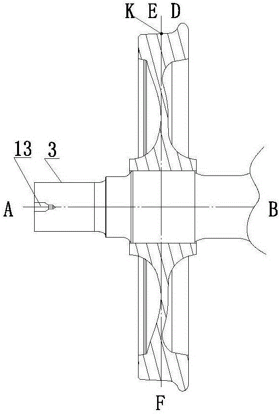
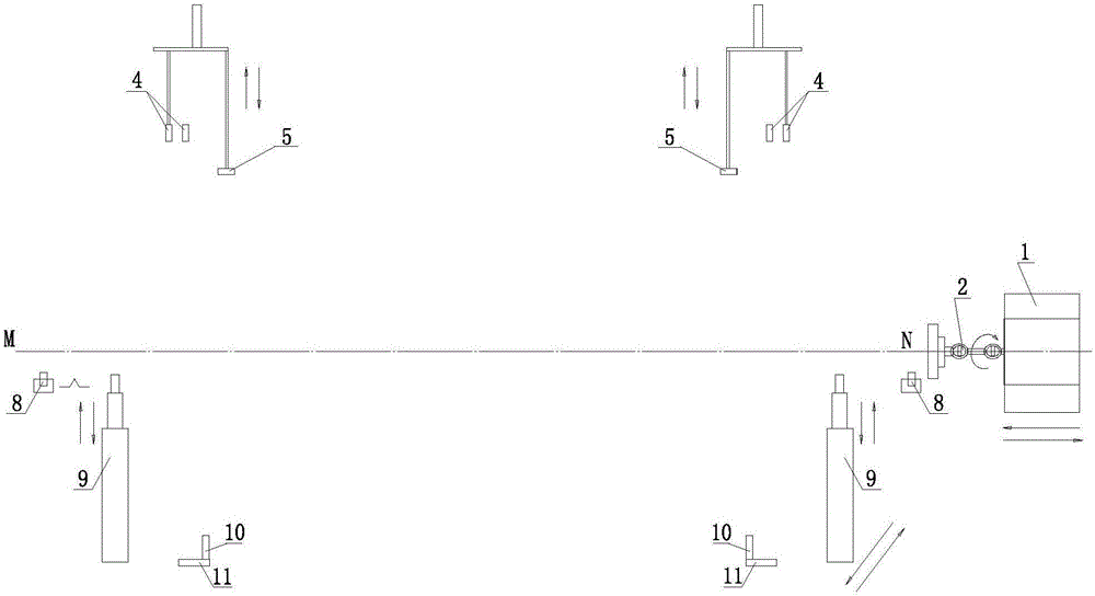
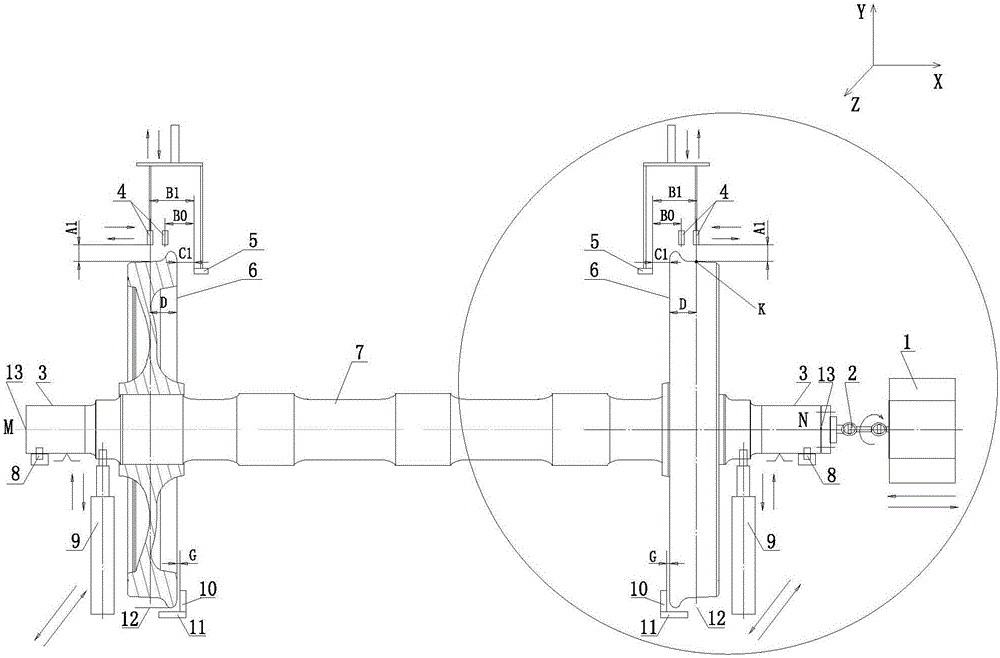
[0041] See attached figure 2 , The measuring device used to measure the radial runout error of the wheel-set tread includes a motor 1, a universal joint 2, a tread radial measuring sensor 4, a wheel inner side measuring sensor 5, a fixed V-shaped positioning support roller 8, an electric lifting automatic Translation device 9, fixed transverse positioning block 10 and fixed track 11; said motor 1 is connected to one end face of wheel set shaft diameter 3 through universal joint 2 and fasteners, and two sets of tread radial measurement sensors 4 are symmetrically arranged , Measure the inner sides 6 of the two wheels of the wheel set 7. Two sets of measuring sensors 5 on the inner side of the wheel are arranged symmetrically to measure the rolling circles of the two wheel treads of the wheel set 7. Two fixed V-shaped positioning support rollers 7 Symmetrical arrangement to s...


PUM


Abstract

An automatic measurement method for a radial runout error of a wheel pair tread belongs to the field for detecting the radial runout error of the wheel pair tread of a rail vehicle. The automatic measurement method aims to settle a problem of incapability of satisfying a measurement index requirement for highest measurement precision of the radial runout error of the wheel pair tread. The method comprises the following steps of through using an outer circumferential surface of wheel pair shaft diameters at two ends of a wheel pair as a supporting positioning reference, making a wheel pair slowly drop on a fixed V-shaped positioning supporting roller without an impact, wherein the shaft end at one side of the wheel pair is connected with a motor through a universal coupling; arranging wheel inside surface measurement sensors on inside surfaces of wheels at two sides of the wheel pair, and arranging tread radial measurement sensors right above tread rolling circles of the wheels at two sides of the wheel pair; starting a motor at the shaft end of the wheel pair, performing real-time measurement on a distance A1 between the tread radial measurement sensor and a top point of the tread rolling circle by the tread radial measurement sensor until measurement on at least one circumference is finished; and obtaining a difference between a highest value and a lowest value as the radial runout error of the wheel pair tread.

Description

Technical field [0001] The invention belongs to the detection field of the radial runout error of the wheel tread of a rail vehicle, and in particular relates to an automatic measurement method for the radial runout error of the wheel tread. Background technique [0002] Due to the machining error and assembly error of the wheelset, when the wheelset rotates around the axle, the center K point of the wheelset tread will produce a slight jump along the radial direction EF of the wheelset and a slight shift along the axis AB of the wheelset. Because the detection accuracy of the high-speed train’s wheel-set tread radial runout error is required to be within 0.1mm, the measurement accuracy of the equipment required to measure the radial runout error should be controlled within three of the tread radial runout detection error. Within one part, the measurement accuracy of the equipment itself should be controlled within about 0.03mm to fully guarantee the 0.1mm measurement requirement...

Claims


Application Information

Patent Timeline
IPC IPC(8): G01M1/22G01M1/04
CPCG01M1/225G01M1/045
Inventor 刘孝峰张爽程国利
Owner CRRC CHANGCHUN RAILWAY VEHICLES CO LTD
Why Eureka
Try Eureka