Lens, manufacturing method of lens, and optical display device

A lens and display technology, applied in optics, lenses, optical components, etc., can solve problems such as dizziness and user visual fatigue, and achieve the effect of enhancing three-dimensional sense and relieving visual fatigue.

Active Publication Date: 2017-03-15
BOE TECH GRP CO LTD +1
View PDF9 Cites 11 Cited by
  • Summary
  • Abstract
  • Description
  • Claims
  • Application Information

AI Technical Summary

Problems solved by technology

When they are used in VR devices, the images displayed on the screen can only be imaged at a fixed distance, and the user can only focus on the image plane at this fixed distance when watching, and long-term viewing will cause the user's vision fatigue, resulting in dizziness

Method used


Image

  • Lens, manufacturing method of lens, and optical display device
  • Lens, manufacturing method of lens, and optical display device
  • Lens, manufacturing method of lens, and optical display device

Examples


Embodiment 1

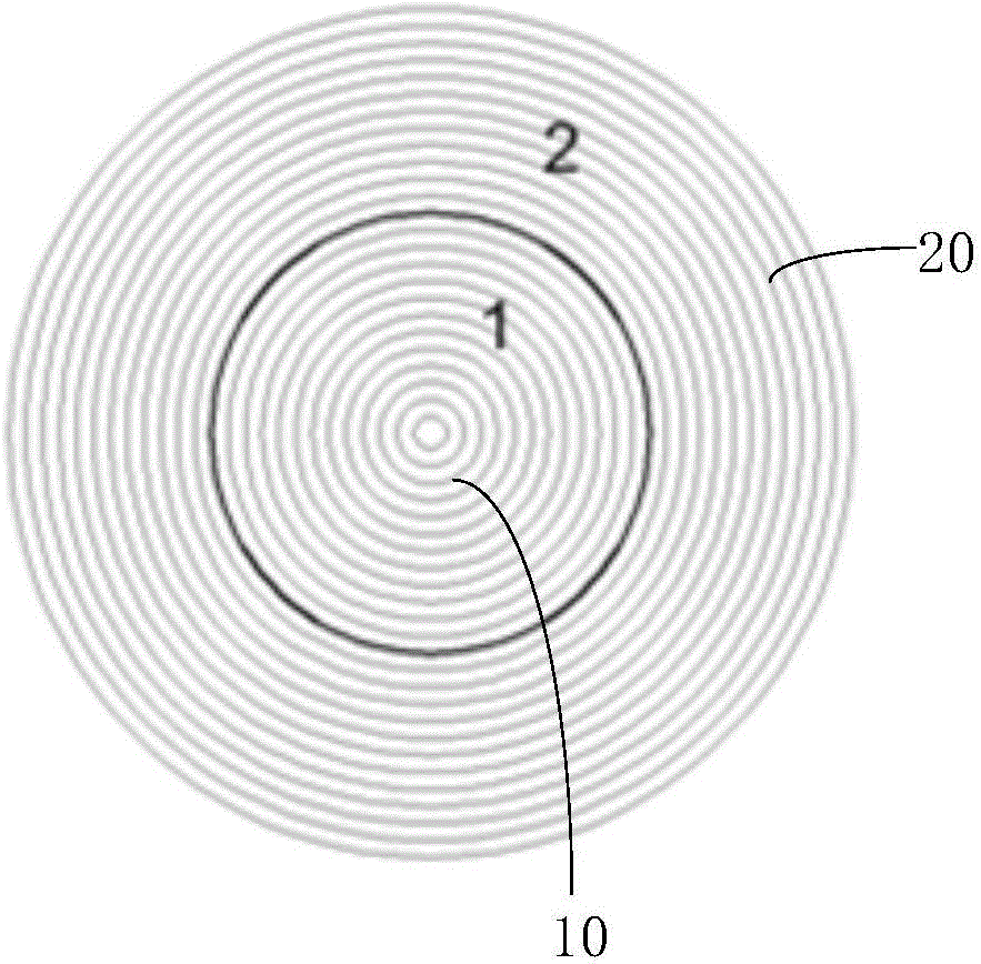
[0038] figure 1 Shown is a schematic structural view of the first embodiment of the lens provided by the present invention.

[0039] Such as figure 1 As shown, in this embodiment, the lens is a circular lens, and one lens area in at least two lens areas is the first lens area 1, and the first lens area 1 is a circular area, which is located in the The central portion of the Fresnel lens; the other lens areas in the at least two lens areas include at least one second lens area 2, which is an annular area surrounding the first lens area 1 .

[0040] With the above solution, the lens can be a circular lens structure, and the lens is divided into different lens areas arranged from inside to outside, wherein one lens area (the first lens area 1) is located at the center of the lens, and the other The lens areas surround the periphery of the first lens area 1 sequentially from the inside to the outside.

[0041]In this embodiment, preferably, when the lens is a Fresnel lens, the...

Embodiment 2

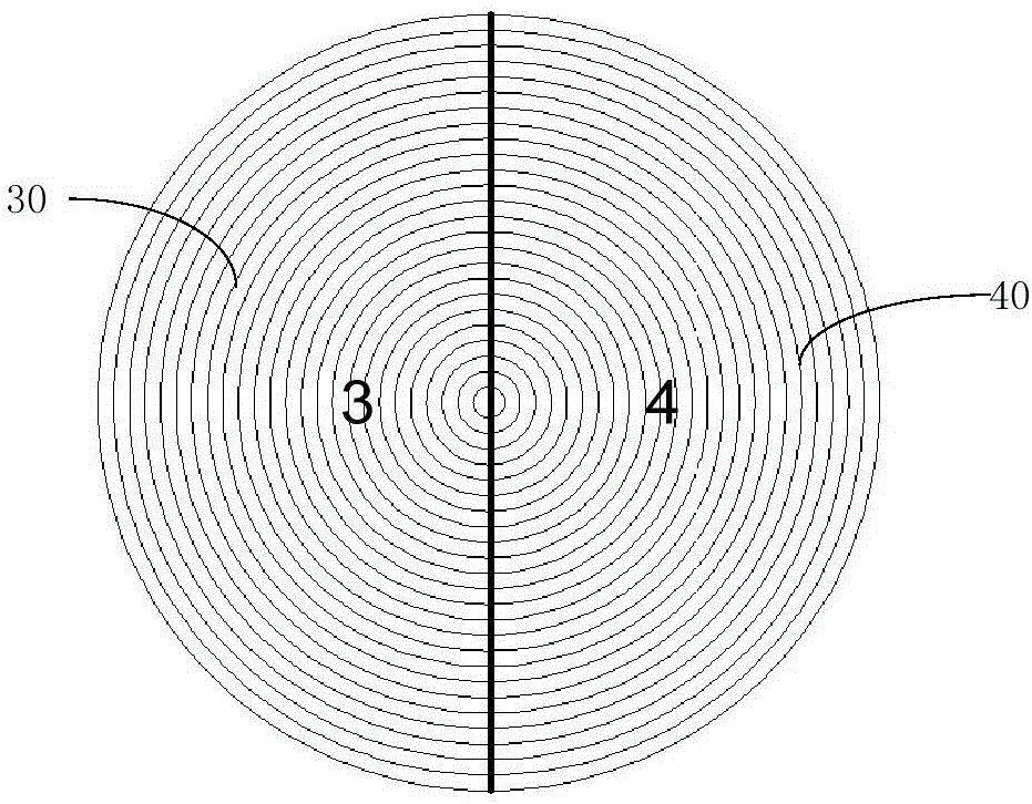
[0046] figure 2 Shown is a schematic structural view of the second embodiment of the lens provided by the present invention.

[0047] In this embodiment, the lens is a circular lens, each of the at least two lens areas is a fan-shaped area, each lens area is provided with arc-shaped tooth patterns, and each The arc-shaped tooth lines in the lens area cooperate to form multiple rings of tooth lines arranged in concentric circles.

[0048] Using the above solution, the lens is divided into a plurality of fan-shaped areas to form different lens areas, wherein each tooth pattern of each fan-shaped area is designed to be arc-shaped, and the arc-shaped tooth lines in each fan-shaped area can be Connect to form a complete ring to form the concentric serrated texture of the Fresnel lens.

[0049] In this embodiment, preferably, at least two lens regions are evenly distributed along the circumference of the circular lens. Using the above solution, the multiple lens areas can be eve...


PUM


Abstract

The present invention provides a lens, a manufacturing method of the lens, and an optical display device. The lens comprises at least two lens regions. The at least two lens regions are different in focal length, so that a real world image is imaged at different preset depths of field when human eyes are looking at the real world image through the at least two lens regions. According to the technical scheme of the invention, the lens comprises different lens regions having different focal lengths, so that the lens is a multi-focal lens. Therefore, when the human eyes are looking at the real world image through the lens, the real world image is imaged at different preset depths of field. When the lens is applied to the imaging process of the optical display device or other virtual reality devices, virtual images seen by the human eyes are imaged at different distances when the human eyes are looking at the image displayed on a screen through different lens regions due to the fact that different lens regions are different in focal length. When the human eyes are looking at the virtual images of different distances for a long period of time, the visual fatigue is relieved. Meanwhile, scene images of different depths can be appreciated at the same time, and the three-dimensional feeling is improved.

Description

technical field [0001] The invention relates to the field of display technology, in particular to a lens, a manufacturing method thereof, and an optical display device. Background technique [0002] In the field of virtual reality (VR, virtual reality), a convex lens is usually used to image the picture displayed on the display screen to 25-50cm in front of the human eye. Since the left and right eyes of the human see different pictures, after processing by the brain, a three-dimensional This is the principle of binocular stereo vision. Traditional convex lenses have only one fixed focal length. When they are used in VR devices, the images displayed on the screen can only be imaged at a fixed distance, and the user can only focus on the image plane at this fixed distance when watching, and long-term viewing will cause the user's vision Fatigue, resulting in dizziness. Contents of the invention [0003] The object of the present invention is to provide a lens and its man...

Claims


Application Information

Patent Timeline
Patent Type & Authority Applications(China)
IPC IPC(8): G02B3/00G02B3/08G02B27/01
CPCG02B3/00G02B3/08G02B27/0101G02B3/10G02B13/02
Inventor 张雪冰陈东张浩陈丽莉董瑞君王晨如刘亚丽
Owner BOE TECH GRP CO LTD
Why Eureka
Try Eureka