Connection structure of airborne electronic equipment and antenna

A technology of airborne electronic equipment and connection structure, which is applied in the direction of antenna, antenna coupling, antenna parts, etc., to achieve the effects of stable structure, improved anti-vibration ability, and enhanced shielding ability

Pending Publication Date: 2017-03-15
CETC AVIONICS
View PDF5 Cites 2 Cited by
  • Summary
  • Abstract
  • Description
  • Claims
  • Application Information

AI Technical Summary

Problems solved by technology

[0005] The purpose of the present invention is to solve the defects existing in the connection mode of the existing airborne electronic equipment and its supporting antenna, and provide a connection structure between the airborne electronic equipment and the a

Method used


Image

  • Connection structure of airborne electronic equipment and antenna
  • Connection structure of airborne electronic equipment and antenna
  • Connection structure of airborne electronic equipment and antenna

Examples


Embodiment

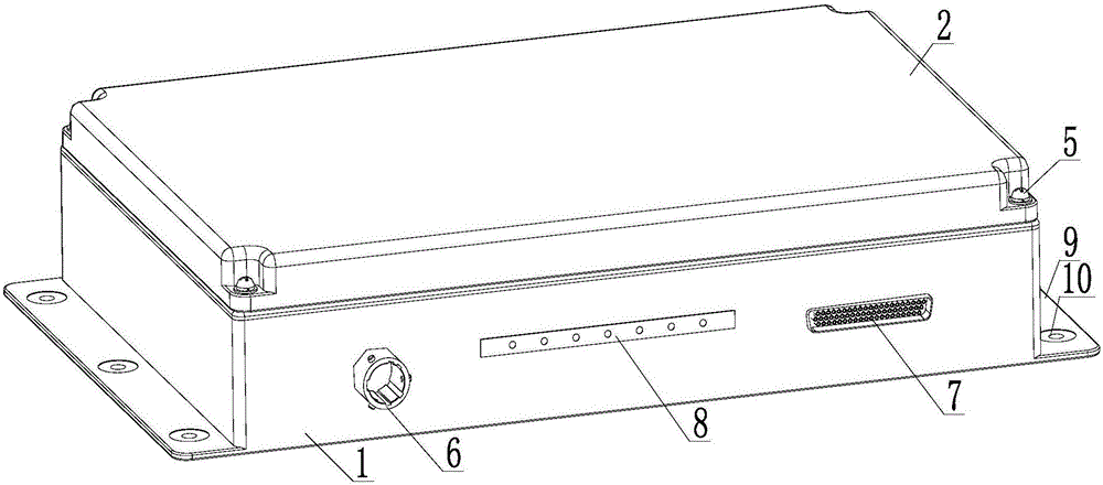
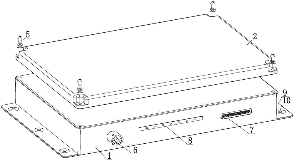
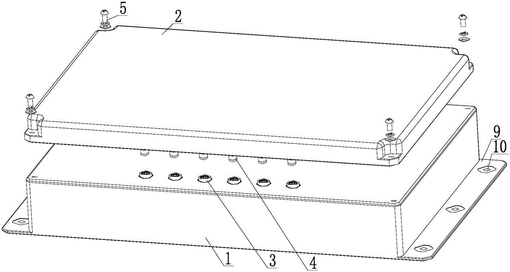
[0028] Such as Figure 1 ~ Figure 3 As shown, a connection structure between an airborne electronic device and an antenna includes an airborne electronic device host 1, a radome 2 and a positioning member 5, wherein the radome 2 is made of a non-metallic material, and an antenna is installed and fixed inside it. The antenna forms an integrated panel antenna under the action of the radome 2 . The chassis of the airborne electronic equipment host 1 and the radome 2 of the present embodiment are rectangular box structures, and the length of the chassis of the airborne electronic equipment host 1 is equal to the length of the radome 2, and the chassis of the airborne electronic equipment host 1 The width is equal to the width of the radome 2 . The four right-angled corners of the radome 2 are provided with positioning perforations, and the four right-angled corners on the upper end surface of the mainframe 1 of the airborne electronic device are concavely formed with positioning ...


PUM


Abstract

The invention discloses a connection structure of airborne electronic equipment and an antenna. The connection structure comprises an airborne electronic equipment host and an antenna housing, wherein the antenna is fixed and arranged in the antenna housing; a first antenna radio frequency connector is fixed on a case of the airborne electronic equipment host; a second antenna radio frequency connector connected with the antenna in antenna housing is fixed on the antenna housing; and the first antenna radio frequency connector is connected with the second antenna radio frequency connector. The antenna is convenient to replace when the connection structure is used; signal coverage performance fluctuation and deterioration caused by antenna arrangement can be reduced; the consistency of the antenna coverage ability is ensured; and the loss can be reduced and the equipment shielding ability can be improved.

Description

technical field [0001] The invention relates to wireless electronic technology, in particular to a connection structure between an airborne electronic device and an antenna. Background technique [0002] With the development of avionics technology, the number of airborne electronic equipment in civil aviation aircraft is increasing. In addition to traditional airborne electronic equipment such as communication and navigation systems, radar ranging systems, and anti-collision warning systems, avionics systems and cabin systems have also been added. , entertainment system, information system and other airborne systems, which also gave birth to the development and application of more airborne electronic equipment and its supporting antenna equipment. [0003] At present, the connection methods of airborne electronic equipment and its supporting antenna mainly adopt two methods: built-in antenna installation and external antenna connection. Among them, in the built-in antenna in...

Claims


Application Information

Patent Timeline
IPC IPC(8): H01Q1/22H01Q1/28H01Q1/42H01Q1/52
CPCH01Q1/22H01Q1/285H01Q1/42H01Q1/526
Inventor 刘学鄢勇
Owner CETC AVIONICS
Why Eureka
Try Eureka