Pin-type connection terminal for high-frequency signal transmission

A high-frequency signal and connection terminal technology, which is applied in the direction of connection, connection device parts, contact parts, etc., can solve problems such as signal loss, crosstalk, and unstable contact interface, so as to reduce signal loss and crosstalk and ensure safety and reliability. The effect of stability and contact interface stability

Active Publication Date: 2017-03-15
SHEN ZHEN TOP LINK TECH CO LTD
View PDF5 Cites 0 Cited by
  • Summary
  • Abstract
  • Description
  • Claims
  • Application Information

AI Technical Summary

Problems solved by technology

[0004] However, since the needle in the existing needle terminal is set in the needle tube, and the spring is received in the needle tube and interferes between the needle and the needle tube, the electrical signal at the external electronic component is transmitted in two parts after passing through the needle. It is transmitted to the needle tube through the spring, and the other part is transmitted to the needle tube through the needle and the inner wall of the needle tube; since the external electronic component is the center of the push needle, it will make the needle and the needle tube slide when the push needle is telescopically sliding on the needle tube. The side wall of the needle is in a non-contact state, which affects the reliability of the contact between the needle and the side wall of the needle tube, thus making the contact interface between the needle and the needle tube unstable and unable to achieve impedance matching, thus causing signal loss and crosstalk during signal transmission. Especially when high-frequency signal transmission is more serious

Method used


Image

  • Pin-type connection terminal for high-frequency signal transmission
  • Pin-type connection terminal for high-frequency signal transmission
  • Pin-type connection terminal for high-frequency signal transmission

Examples


Embodiment Construction

[0021] In order to describe the technical content and structural features of the present invention in detail, further description will be given below in conjunction with the implementation and accompanying drawings.

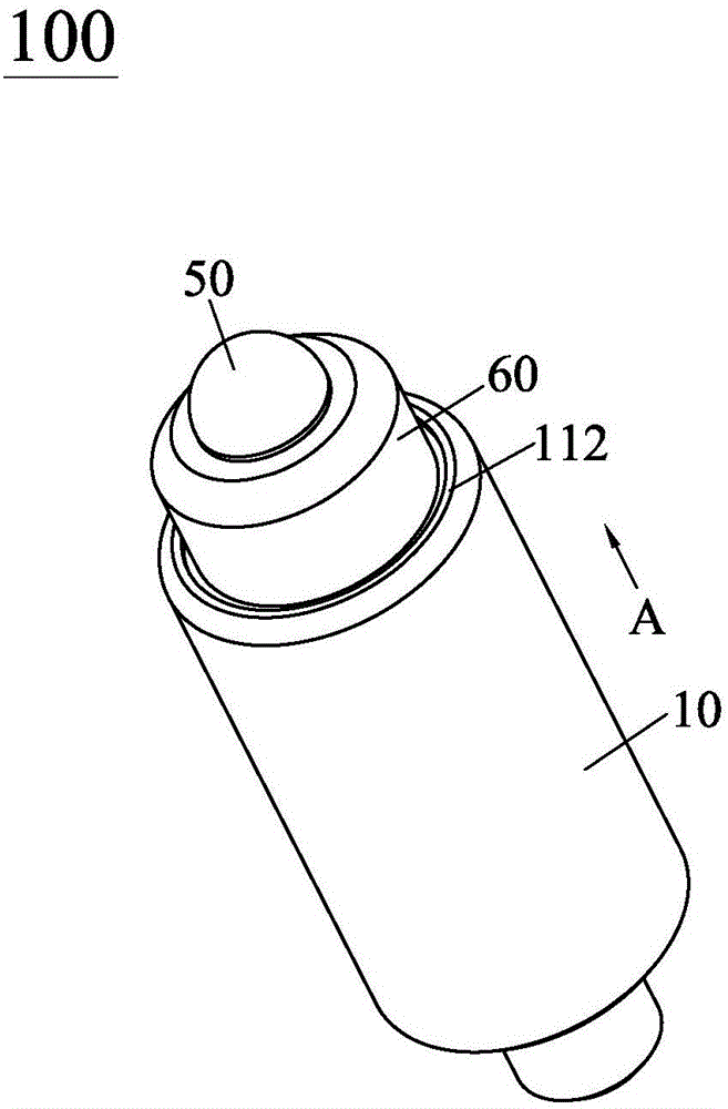
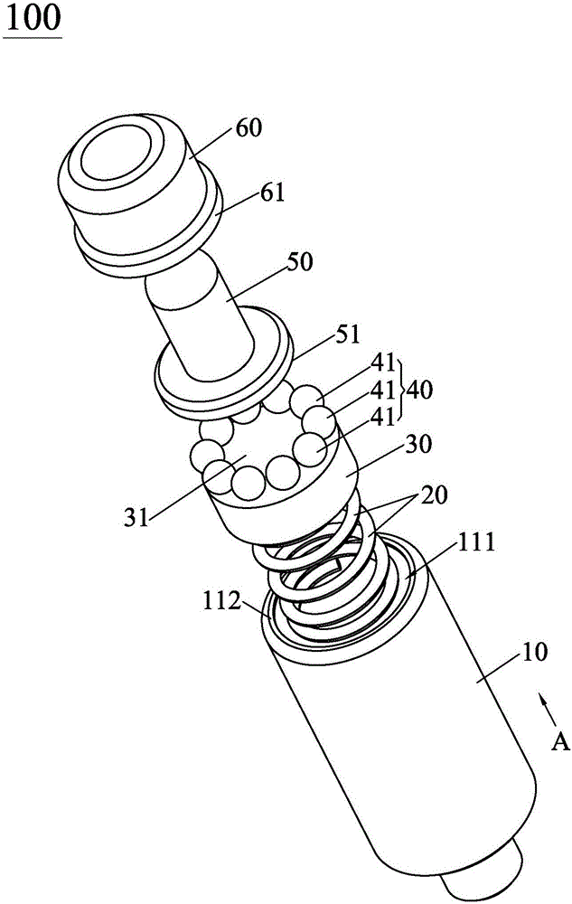
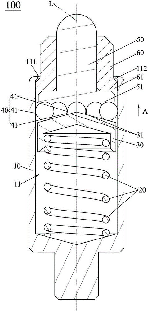
[0022] see figure 1 and figure 2 , The high-frequency signal transmission pin-type connection terminal 100 of the present invention includes a conductive needle tube 10, an elastic member 20, a first insulator 30, a conductive ball set 40, a conductive needle head 50 and a second insulator 60 . The needle tube 10 has a housing cavity 11, the housing cavity 11 runs through one end of the needle tube 10 along the axial direction of the needle tube 10 (i.e. the direction indicated by the arrow A) and forms a cavity 111, so that the elastic member 20, the first insulator 30, the ball assembly 40 , the needle 50 and the second insulator 60 are assembled into the receiving cavity 11 from the cavity opening 111 . The elastic member 20 is placed in the housing cavity...


PUM


Abstract

The invention provides a pin-type connection terminal for high-frequency signal transmission. The pin-type connection terminal comprises a pin tube with an accommodating cavity, an elastic part, a first insulator, a ball group, a pin head and a second insulator, wherein a first end of the elastic part is elastically propped against the pin tube and a second end extends towards a cavity opening along the axial direction of the pin tube; the first end of the first insulator is elastically propped against the second end of the elastic part and the second end is provided with a conical surface which is high in middle and low in periphery; all balls in the ball group surround the conical surface and are propped against the conical surface; the first end of the pin head is propped against the ball group and the second end extends out of the cavity opening along the axial direction of the pin tube; and the second insulator sleeves the pin head and separates the pin head from the pin tube. The conical surface pushes the ball group to be propped between the pin head and the pin tube under the elasticity of the elastic part, thereby achieving electrical conduction of the pin head, the ball group and the pin tube; and the signal loss and crosstalk are reduced during high-frequency signal transmission, thereby ensuring the security and the reliability of the high-frequency signal transmission.

Description

technical field [0001] The invention relates to a terminal for signal transmission, in particular to a pin-type connection terminal for high-frequency signal transmission with a stable contact interface. Background technique [0002] The pin terminal is a core component used in precision connectors in the fields of mobile phones, communications, automobiles, medical, aerospace and other fields. The pin terminal is used to realize the electrical connection between the precision connector and external electronic components. So as to play the normal function of the precision connector. [0003] As we all know, a needle terminal generally includes a needle, a needle tube and a spring. The purpose of electrical connection is achieved by the elastic resistance of the external electronic components. [0004] However, since the needle in the existing needle terminal is set in the needle tube, and the spring is received in the needle tube and interferes between the needle and the n...

Claims


Application Information

Patent Timeline
Patent Type & Authority Applications(China)
IPC IPC(8): H01R13/6461H01R13/17
CPCH01R13/17H01R13/6461H01R13/2421
Inventor 肖岚唐毅
Owner SHEN ZHEN TOP LINK TECH CO LTD
Why Eureka
Try Eureka