Supercharge Your Innovation With Domain-Expert AI Agents!

Computer lifting desk

A technology of lifting desks and computers, which is applied to desks or desks of computer workstations, desks, desks with variable desk heights, etc., which can solve the problems of large space occupation, complicated adjustment structure, and inconvenient installation, and achieve simple and firm structure. , the effect of compact structure

Inactive Publication Date: 2017-03-22
范佳欣
View PDF22 Cites 2 Cited by
  • Summary
  • Abstract
  • Description
  • Claims
  • Application Information

AI Technical Summary

Problems solved by technology

[0002] Existing computer desks usually have a fixed height, and their desktops cannot be adjusted according to needs. However, some computer desks that can be adjusted in height usually have a complicated adjustment structure and are very inconvenient to install, which makes the overall structure of the desk very heavy and takes up a lot of space.

Method used


Image

  • Computer lifting desk
  • Computer lifting desk
  • Computer lifting desk

Examples


Embodiment 1

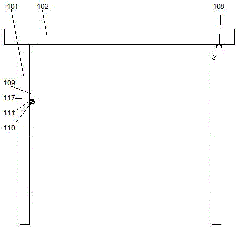
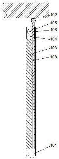
[0023] In this example, if image 3 As shown, when the computer is placed on the side of the desktop, in order to facilitate the adjustment of the angle of the desktop, the position where the computer is placed can be tilted. The bar can rotate horizontally relative to the desktop, and at the same time, a pin shaft 112 is provided in the middle of the desktop 102, so that the desktop is made of two parts, one part of which is used to place the computer, so that the pin shaft 112 is parallel to the axial direction of the rotating shaft 105, and the desktop 102 is 2 pieces The structure of the panel 113 is formed by hinged with each other through the pin shaft 112, so that the two panels can rotate with each other and tilt at a certain angle; A connecting plate is arranged on the lower end surface of the panel on one side of the baffle, and when the height of the screw is adjusted, the screw can push the panel to rotate around the pin, so that the panel near the rear baffle is i...

Embodiment 2

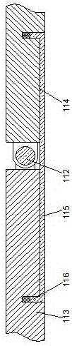
[0027] In this embodiment, in order to facilitate the installation of bayonet pins, preferably, a through groove is provided on the lower end surface of the connecting plate 109, and a positioning pin 117 is provided inside the through groove, so that the axis of the positioning pin is parallel to the axis of the rotating shaft. Set the bayonet pin 110 on the positioning pin 117, so that the bayonet pin can rotate around the positioning pin, and a torsion spring is arranged on the positioning pin 117, so that one end of the torsion spring is fixedly connected to the inner wall of the through groove, and the other end of the torsion spring is fixedly connected to the inner wall of the slot. On the detent 110 , the detent 110 is plugged between the corresponding detents 111 when the torsion spring is in a natural state. When the desktop is moved, the desktop drives the connecting plate to move longitudinally. At this time, the locking pin arranged under the connecting plate will ...


PUM


Abstract

The invention discloses a computer lifting desk which comprises a support and a desk top arranged at the upper end of the support. A rear baffle plate is arranged at one end of the support, a cavity is formed in the inner side of the rear baffle plate, a rotating shaft is arranged in the cavity along the length direction of the rear baffle plate, two ends of the rotating shaft are respectively rotatably connected onto the side wall of the cavity, gears are arranged at two ends of the rotating shaft respectively, positioning holes are formed in the inner side of the cavity, internal threads are arranged on the inner walls of the positioning holes, lead screws engaged with the gears are arranged in the positioning holes, one end of each rotating shaft penetrates the side wall of the cavity and extends out of the outer side of the side wall of the rear baffle plate, and handles are arranged at ends of the rotating shafts. A lead screw mechanism drives the rear side of the desk top to move, the front of the desk top is positioned by clamp pins, the integral structure is simple, and the height of the computer lifting desk is conveniently adjusted.

Description

technical field [0001] The invention relates to a computer lifting table. Background technique [0002] Existing computer desks usually have a fixed height, and their desktops cannot be adjusted according to needs. However, some computer desks that can be adjusted in height usually have a complicated adjustment structure and are very inconvenient to install, which makes the overall structure of the desk very heavy and takes up a lot of space. . Contents of the invention [0003] The purpose of the present invention is to provide a computer lifting table, which can improve the problems existing in the prior art. By using the screw mechanism to drive the table top to move, and using the four-bar mechanism to push the back side of the table to move, the bayonet can be aligned with the front of Zhuo Ming. The whole body is positioned, the overall structure is simple, and the height is easy to adjust. [0004] The present invention is realized through the following technical ...

Claims


Application Information

Patent Timeline
IPC IPC(8): A47B9/04A47B21/02
CPCA47B9/04A47B21/02A47B2009/043
Inventor 范佳欣
Owner 范佳欣
Features
  • R&D
  • Intellectual Property
  • Life Sciences
  • Materials
  • Tech Scout
  • Unparalleled Data Quality
  • Higher Quality Content
  • 60% Fewer Hallucinations
Learn More