Transurethral surgical robot and control system

A surgical robot and control system technology, applied in surgical robots and other directions, can solve problems such as difficulty in meeting technical requirements

Inactive Publication Date: 2017-03-22
SECOND MILITARY MEDICAL UNIV OF THE PEOPLES LIBERATION ARMY
View PDF8 Cites 21 Cited by
  • Summary
  • Abstract
  • Description
  • Claims
  • Application Information

AI Technical Summary

Problems solved by technology

At present, most of the existing surgical robots, including da Vinci, are difficult to meet the technical requirements of surgery through the natural orifice of the human ...

Method used


Image

  • Transurethral surgical robot and control system
  • Transurethral surgical robot and control system
  • Transurethral surgical robot and control system

Examples


Embodiment 1

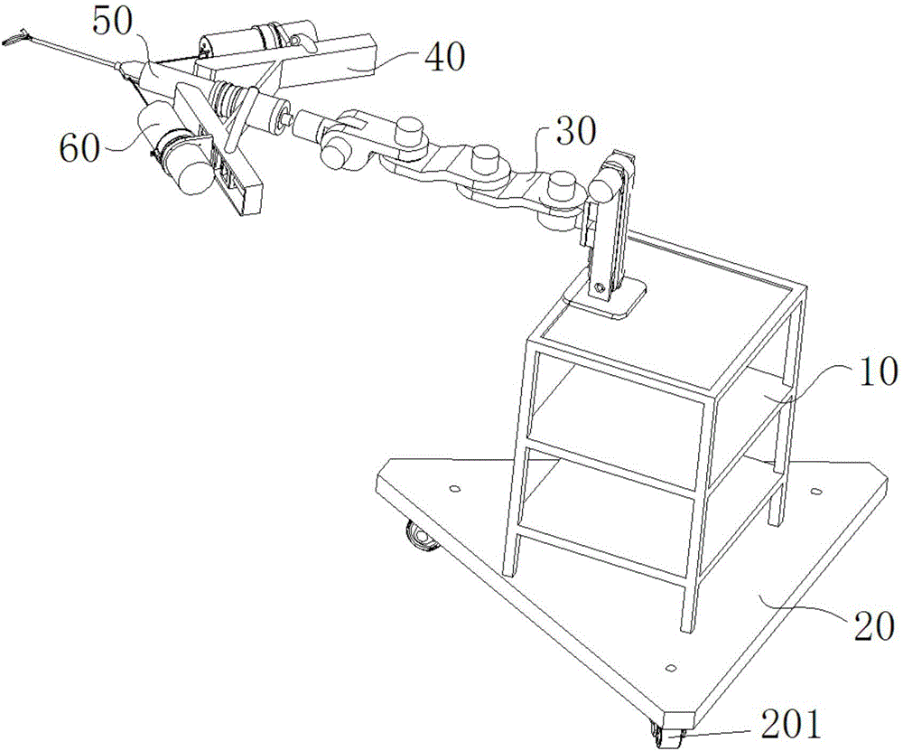
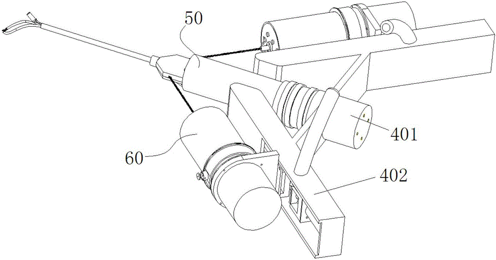
[0039] like Figure 1~3 As shown, the present embodiment includes a frame 10, a chassis 20 is fixedly connected to the bottom of the frame 10, a support 40 is connected to the top of the frame 10 through a transmission chain 30, and a cystoscope 50 and a cystoscope 50 are fixedly connected to the support 40. Two surgical tools 60 .

[0040] like Figure 4 As shown, the cystoscope 50 includes a mirror body 501 and a mirror body driving unit 502 .

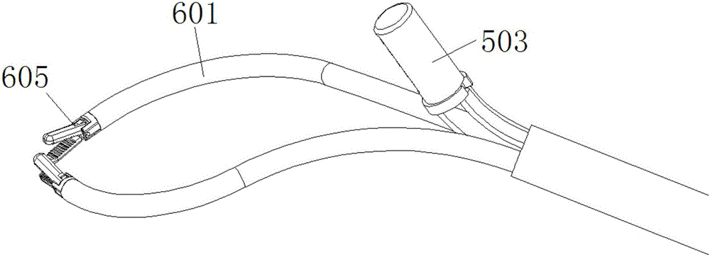
[0041] like Figure 4 , Figure 5As shown, the mirror body 501 includes a high-definition camera 503 carrying an illumination module, a fixed plate 504, two first structural bones 505, a second structural bone 506, a support member 507 and a thin-walled tube 508 with a circular cross section . Wherein, the two first structural bones 505 and one second structural bone 506 are evenly distributed in a triangular shape, and the front ends of the three are jointly fastened to one side of the fixing plate 504 . The other side of the ...

Embodiment 2

[0056] like Figure 22 As shown, in this embodiment, a control terminal 70 and a control cabinet 80 are added on the basis of the first embodiment. The control terminal 70 includes an upper computer 701, a display 702, two remote control devices 703 and two pedals 704, wherein the display 702, two remote control devices 703 and two pedals 704 are all electrically connected to the upper computer 701. The control cabinet 80 includes an industrial computer 801 , an adapter board 802 , multiple motor drivers 803 and a display 804 . The industrial computer 801 is electrically connected to the upper computer 701 and the adapter board 802 respectively, and the adapter board 802 is electrically connected to the motor driver 803 , the display 702 , the display 804 , and the cable 509 of the high-definition camera 503 . Each motor driver 803 is electrically connected to the motor 405 , the motor 303 , the motor 307 , the motor 309 , the motor 311 , the motor 313 , and the motor 315 . ...


PUM


Abstract

The invention relates to a transurethral surgical robot and control system. The transurethral surgical robot and control system comprises a rack, the bottom of the rack is fixedly connected with a chassis, the top of the rack is connected with a support through a transmission chain, and the support is fixedly connected with a cystoscope and two surgical tools. Each surgical tool comprises a flexible continuous body mechanical arm and a mechanical arm driving device. The support comprises a cystoscope mounting seat and two surgical tool mounting seats. The cystoscope mounting seat is fixedly connected with the cystoscope. Each surgical tool mounting seat is connected with a vertical plate through a straight-line motion mechanism, the front side of each vertical plate is fixedly connected with a connecting outer cover, and the rear side of each vertical plate is fixedly connected with a plurality of first motors used for conducting turning control over the corresponding flexible continuous body mechanical arm. The transurethral surgical robot further comprises a control cabinet. The control cabinet comprises an industrial computer, an adapter plate, a plurality of motor drivers and a first displayer. The industrial computer is electrically connected with the adapter plate, and the adapter plate is electrically connected with the motor drivers and the first displayer. The motor drivers are electrically connected with the first motors correspondingly.

Description

technical field [0001] The invention relates to a transurethral surgical robot and a control system, belonging to the field of medical instruments. Background technique [0002] In the modern medical field, minimally invasive surgery has achieved success in reducing patients' postoperative pain and complications, shortening hospital stay, and improving postoperative scar conditions. In this field, the da Vinci porous laparoscopic surgical robot developed by Intuitive Surgical, which has been successfully commercialized, can meet the requirements of various minimally invasive surgeries. However, with the maturity of medical technology and the higher and higher requirements of patients, there has been naturalorifice trans-luminal endoscopic surgery (NOTES), which is characterized by the fact that no incision is required, and surgical instruments need to pass through a long and narrow cavity. The complex human cavity then arrives at the surgery department for operations such a...

Claims


Application Information

Patent Timeline
IPC IPC(8): A61B34/30
Inventor 孙颖浩徐凯赵江然戴正晨肖亮
Owner SECOND MILITARY MEDICAL UNIV OF THE PEOPLES LIBERATION ARMY
Why Eureka
Try Eureka