
Ship bilge keel positioning and mounting method

A positioning installation and bilge keel technology, which is applied to ship components, ship construction, ship design, etc., can solve the problems of large installation position error, large deviation, and difficulty in confirming whether the installation angle is correct, and achieve linear accuracy to avoid , Guarantee installation accuracy and reduce installation difficulty

Active Publication Date: 2017-03-22
JIANGNAN SHIPYARD GRP CO LTD
View PDF4 Cites 16 Cited by
  • Summary
  • Abstract
  • Description
  • Claims
  • Application Information

AI Technical Summary

Problems solved by technology

[0003] In view of the above-mentioned shortcomings of the prior art, the purpose of the present invention is to provide a method for positioning and installing the bilge keel of a ship, which is used to solve the problem that the positioning method for installing the hull of the bilge keel in the prior art is not accurate enough, and the error of the installation position is relatively large, resulting in subsequent loading. The installation position of the bilge keel is discontinuous and has large deviations in the stage; there is no basis for angle positioning in the process of installing the bilge keel, and the rough construction can only be carried out based on the structure, and it is difficult to confirm whether the installation angle is correct in the follow-up accuracy; the stage of the bilge keel is not clearly given Installation accuracy requirements, the problem that it is impossible to give a clear judgment on whether the installation results meet the performance requirements of the bilge keel

Method used


Image

  • Ship bilge keel positioning and mounting method
  • Ship bilge keel positioning and mounting method
  • Ship bilge keel positioning and mounting method

Examples


Embodiment Construction

[0042] Embodiments of the present invention are described below through specific examples, and those skilled in the art can easily understand other advantages and effects of the present invention from the content disclosed in this specification. The present invention can also be implemented or applied through other different specific implementation modes, and various modifications or changes can be made to the details in this specification based on different viewpoints and applications without departing from the spirit of the present invention. It should be noted that, in the case of no conflict, the following embodiments and features in the embodiments can be combined with each other.

[0043] It should be noted that the diagrams provided in the following embodiments are only schematically illustrating the basic ideas of the present invention, and only the components related to the present invention are shown in the diagrams rather than the number, shape and shape of the compo...


PUM


Abstract

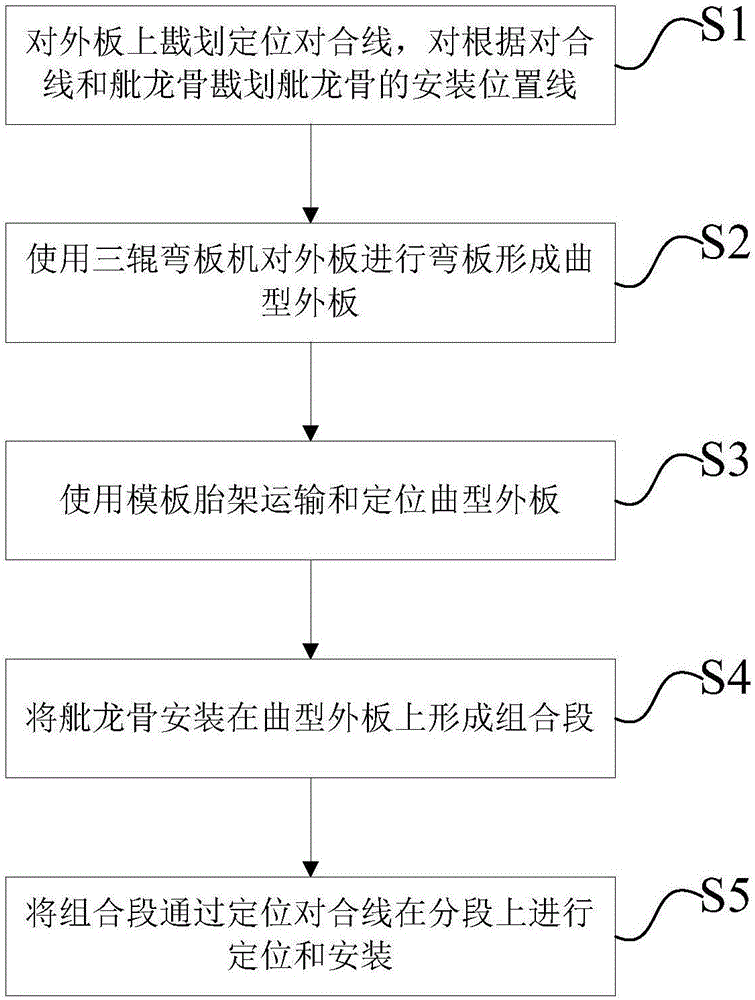
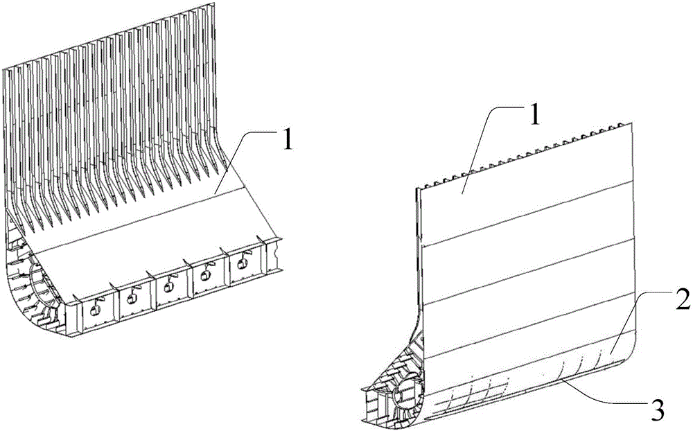
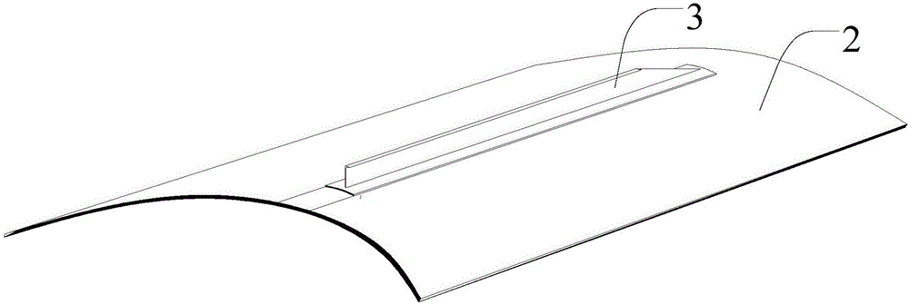
The invention provides a ship bilge keel positioning and mounting method. A bilge keel is mounted on an outer curved plate which is positioned in a bilge section. The method includes steps: S1, marking a positioning joining line on the outer plate, and marking a bilge keel mounting position line according to the positioning joining line and the bilge keel; S2, adopting a three-roll plate bending machine for linear curvature processing of the outer plate to form the outer curved plate; S3, using a moulding bed for transporting and positioning the outer curved plate; S4, mounting the bilge keel on the outer curved plate to form a combined section; S5, positioning and mounting the combined section on the bilge section according to the positioning joining line. At a bilge keel mounting stage, after completion of a large section group, curvature processing of the outer plate of the bilge section is performed before mounting of the bilge keel. A normal-posture faceup installation way of the bilge keel is optimized into a horizontal faceup installation way to lower installation difficulty. Bilge keel installation precision is optimized from rough installation to accuracy control, subsequent reworking is avoided due to angle control of the bilge keel, and the moulding bed guarantees linear precision of the outer curved plate in a placement and transport process to avoid subsequent reworking.

Description

technical field [0001] The invention relates to the field of ship building, in particular to a method for positioning and installing a ship bilge keel Background technique [0002] At present, the research on the implementation method for the precise positioning and installation of the bilge keel of large ships has not been involved in China. Technically, the design drawings only give a brief description of the installation position and installation angle of the bilge keel for large ships, but do not give the positioning and installation methods and installation standards for the bilge keel of large ships. After systematically studying the relevant data on the characteristics of marine bilge keels for various types of ships, and analyzing from the perspective of installation technology, the current positioning and installation methods and installation effects are not comprehensive enough, and there are the following deficiencies: 1) The hull positioning method for bilge keel...

Claims


Application Information

Patent Timeline
Patent Type & Authority Applications(China)
IPC IPC(8): B63B9/00
CPCB63B71/00B63B2221/02
Inventor 常志军郭俊林孙少华黄健王钰孙旭梁崇轩龚松凯
Owner JIANGNAN SHIPYARD GRP CO LTD
Learn More