Steel-structure waterproof jointing plate of well wall and construction process of steel-structure waterproof jointing plate

A construction technology and steel structure technology, which is applied to shaft equipment, shaft lining, mining equipment, etc., can solve the problems of the interface sealing performance failing to meet the construction requirements, the poor waterproof effect of the shaft wall, and the increasing difficulty of grouting. Achieve good waterproof effect, increase compactness, and facilitate construction.

Inactive Publication Date: 2017-03-22
CHINA UNIV OF MINING & TECH
View PDF10 Cites 5 Cited by
  • Summary
  • Abstract
  • Description
  • Claims
  • Application Information

AI Technical Summary

Problems solved by technology

[0004] Research and practice have shown that the first two schemes (1) and (2) are difficult to make the interface strength reach the strength of the concrete body, and the sealing performance of the interface cannot meet the construction requirements; the scheme (3) specifically involves a Chinese invention patent , whose publication number is CN101550833A, specifically discloses a cast-in-place concrete stubble slab and its construction technology, which adopts section-by-section construction, and sets a ring-shaped or square-shaped stubble slab connected between every two sections of cast-in-place concrete stubble joints , this scheme improves the bonding strength and airtightness of new and old concrete to a certain extent, but the actual use effect is still not good. When the pores and seepage channels are formed on the contact surface of the recommended slab and its upper and lower concrete due to the construction process, the grouting method used cannot effectively fill the seepage channel and the nearby pores between the stubble slab and the concrete contact surface with grout, resulting in the The waterproof effect of the wall is not good, and the difficulty of grouting is increased, etc.

Method used


Image

  • Steel-structure waterproof jointing plate of well wall and construction process of steel-structure waterproof jointing plate
  • Steel-structure waterproof jointing plate of well wall and construction process of steel-structure waterproof jointing plate
  • Steel-structure waterproof jointing plate of well wall and construction process of steel-structure waterproof jointing plate

Examples


Embodiment Construction

[0015] In order to make the purpose, technical solutions and advantages of the embodiments of the present invention clearer, the technical solutions in the embodiments of the present invention will be clearly and completely described below in conjunction with the drawings in the embodiments of the present invention. Obviously, the described embodiments It is a part of embodiments of the present invention, but not all embodiments. Based on the embodiments of the present invention, all other embodiments obtained by persons of ordinary skill in the art without making creative efforts belong to the protection scope of the present invention.

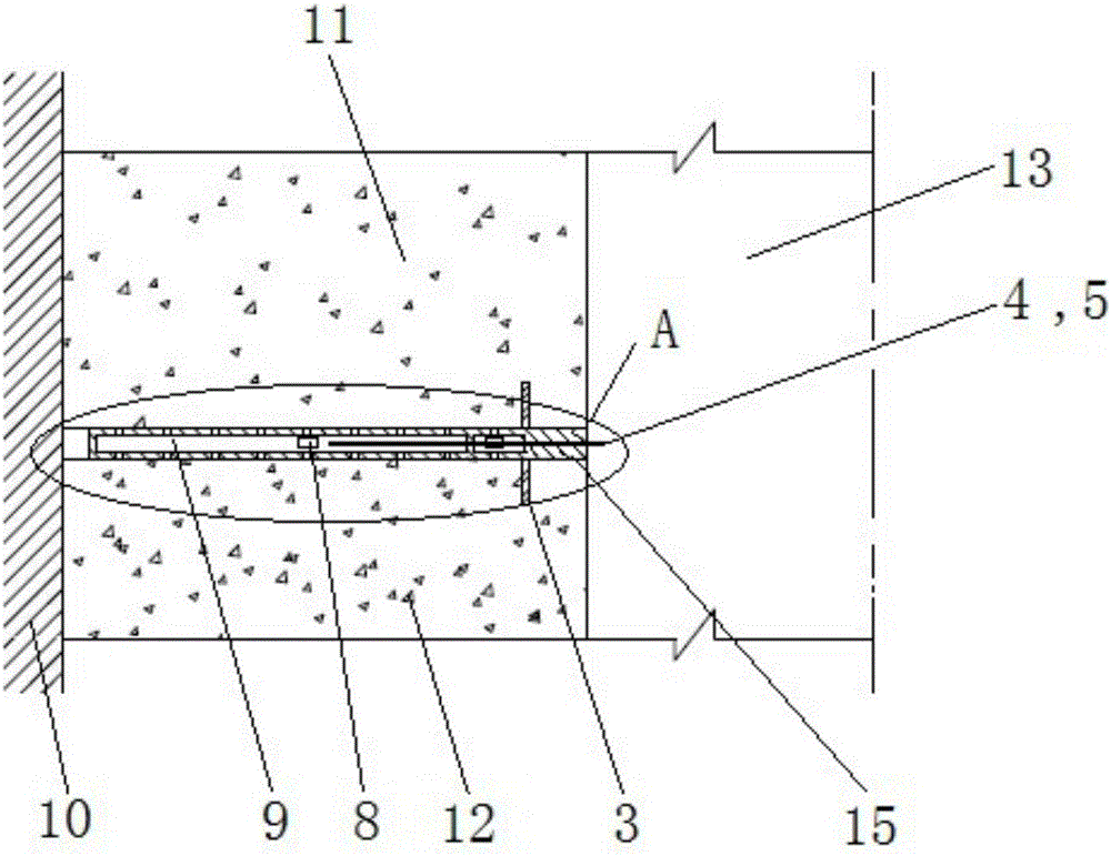
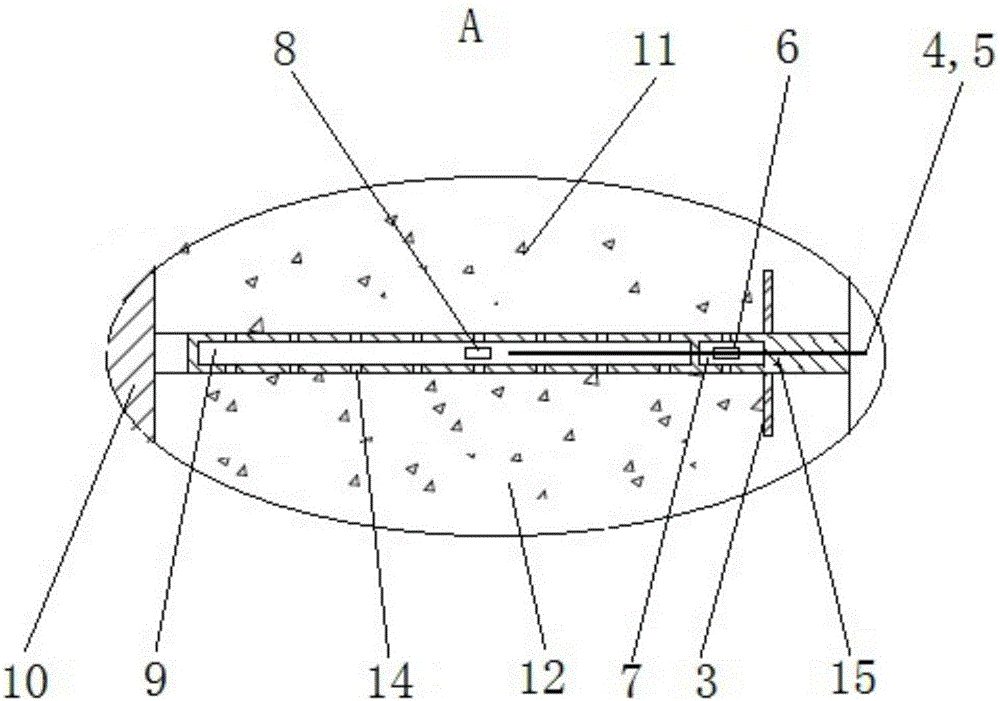
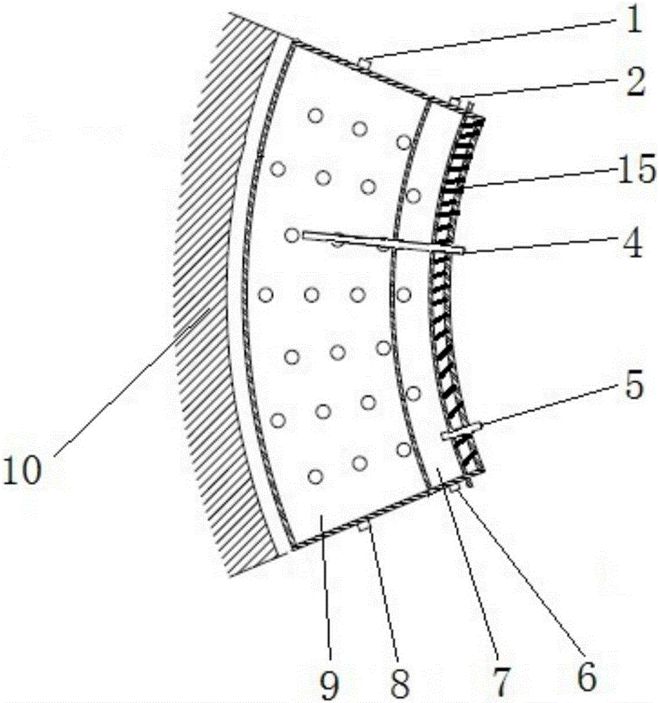
[0016] figure 1 and image 3 It shows a schematic structural diagram of a preferred embodiment of the present invention, and the structure is analyzed in detail from the horizontal and vertical spaces, Figure 1 to Figure 3 A kind of steel structure waterproof stubble board for well wall, said steel structure waterproof stubble board is a m...


PUM


Abstract

The invention provides a steel-structure waterproof jointing plate of a well wall and a construction process of the steel-structure waterproof jointing plate. The steel-structure waterproof jointing plate is of a multi-cavity annular steel structure laid between cast-in-place concrete of segment construction; the multi-cavity annular steel structure is formed by connecting and surrounding of a plurality of arc sections of multi-cavity annular steel structures in sequence; each arc section of the multi-cavity annular steel structure comprises a grouting cavity, a check valve hole, a water stopping and grout stopping plate and a communication pipe; each multi-cavity annular steel structure is internally provided with a grouting pipe; every two arc sections of the multi-cavity annular steel structures are connected with the water stopping and grout stopping plate through the communication pipe, and a grouting material is injected into each grouting cavity through the grouting pipe; and the grouting material flows to the jointing plate, a connecting surface of upper and lower well walls and an adjacent gap through the check valve hole. According to the steel-structure waterproof jointing plate provided by the invention, the compaction of the jointing plate on a new and old concrete interface and the concrete is increased, and the impervious performance of the new and old concrete interface is improved; and the steel-structure waterproof jointing plate has a good waterproof effect, is simple in structure, convenient to construct and good in sealing performance, and has wider practicability in the technical field.

Description

technical field [0001] The invention relates to a shaft wall steel structure waterproof stubble board and a construction process thereof, which is suitable for various mine shaft walls, and is especially suitable for single-layer shaft walls that adopt segmental downward operation in freezing method construction. Background technique [0002] In the sub-section down-sinking construction of the freezing method, due to the sequence of concrete pouring, the hardening degree of new and old concrete is different to form a weak surface, which has the disadvantages of low bond strength, poor sealing performance, poor impermeability, etc. Therefore, it provides a channel for the seepage of groundwater, and in severe cases, it will cause the well wall to be unusable due to excessive water inflow. [0003] In order to improve the bonding strength and sealing performance of new and old concrete, the existing methods are: (1) Improve the bonding strength of the new and old concrete join...

Claims


Application Information

Patent Timeline
Patent Type & Authority Applications(China)
IPC IPC(8): E21D5/11
CPCE21D5/11
Inventor 任彦龙周来应杨维好
Owner CHINA UNIV OF MINING & TECH
Why Eureka
Try Eureka