Scroll compressor and its fixed scroll and upper cover assembly

A static scroll and assembly technology, applied in the field of compression equipment, can solve the problems of increasing the production cost of scroll compressors, high requirements for installation and positioning accuracy, and affecting the reliability of compressors, etc., to achieve easy processing and safe and reliable welding , The effect of reducing the demand for installation positioning accuracy

Active Publication Date: 2019-01-25
ZHUHAI GREE REFRIGERATION TECH CENT OF ENERGY SAVING & ENVIRONMENTAL PROTECTION
View PDF6 Cites 0 Cited by
  • Summary
  • Abstract
  • Description
  • Claims
  • Application Information

AI Technical Summary

Problems solved by technology

Since the enthalpy increasing tube needs to be connected to the enthalpy increasing hole and the through hole on the upper cover for the enthalpy increasing tube to pass through, the welding liquid can easily flow into the compressor through the through hole along the enthalpy increasing tube; and, the through hole and the enthalpy increasing hole The requirements for installation and positioning accuracy are relatively high, especially the upper cover is also connected with an axially arranged suction pipe similar to the connection and sealing form of the enthalpy-increasing pipe, which greatly increases the accuracy requirements and increases the production cost of the scroll compressor; and , if the suction pipe or enthalpy pipe is not installed properly, the vibration on the pump body in the compressor will be transmitted through these pipes, which will aggravate the vibration of the pipe and affect the reliability of the compressor

Method used


Image

  • Scroll compressor and its fixed scroll and upper cover assembly
  • Scroll compressor and its fixed scroll and upper cover assembly
  • Scroll compressor and its fixed scroll and upper cover assembly

Examples


Embodiment Construction

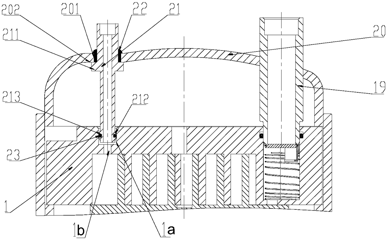
[0042] The invention discloses an assembly of a fixed scroll and an upper cover to ensure safe and reliable welding and reduce precision requirements and vibration. The present invention also provides a scroll compressor with the above-mentioned fixed scroll and upper cover assembly.

[0043] The following will clearly and completely describe the technical solutions in the embodiments of the present invention with reference to the accompanying drawings in the embodiments of the present invention. Obviously, the described embodiments are only some, not all, embodiments of the present invention. Based on the embodiments of the present invention, all other embodiments obtained by persons of ordinary skill in the art without making creative efforts belong to the protection scope of the present invention.

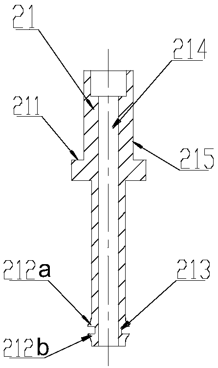
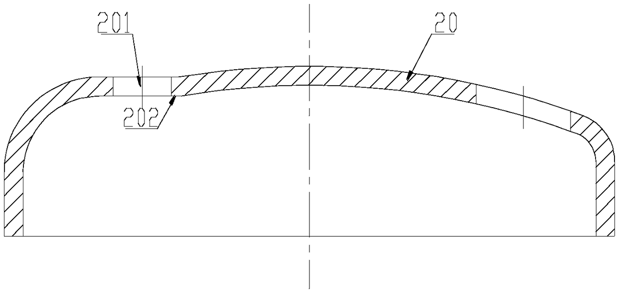
[0044] The invention provides a fixed scroll and upper cover assembly, including a fixed scroll 1, an upper cover 20 and a connecting pipeline structure connecting the fixed scr...


PUM


Abstract

The invention discloses a scroll compressor and a stationary scroll plate and upper cover assembly of the scroll compressor. The stationary scroll plate and upper cover assembly comprises a stationary scroll plate (1), an upper cover (20) and a pipeline connecting structure connected with the stationary scroll plate (1) and the upper cover (20). A through hole (201) which allows the pipeline connecting structure to penetrate through is formed in the upper cover (20). A stationary plate connecting hole (1a) connected with the pipeline connecting structure is formed in the stationary scroll plate (1). An anti-thrust structure (211) is arranged on the pipeline connecting structure. The through hole (201) is covered by the projection of the anti-thrust structure (211) towards the upper cover (20). The outer diameter of an upper pipe section (215), located on the anti-thrust structure (211) and far away from the stationary scroll plate (1), of the pipeline connecting structure is smaller than the inner diameter of the through hole (201). According to the stationary scroll plate and upper cover assembly, welding safety and reliability are guaranteed, the need of installation positional accuracy between the through hole (201) and the stationary plate connecting hole (1a) is reduced, production cost is reduced, and vibration of the pipeline connecting structure is reduced.

Description

technical field [0001] The invention relates to the technical field of compression equipment, in particular to a scroll compressor, a fixed scroll disk and an upper cover assembly thereof. Background technique [0002] Scroll compressors have been widely used due to their advantages of high efficiency, energy saving, low noise and high reliability, especially enthalpy-enhancing scroll compressors. [0003] In order to introduce the external refrigerant into the compression chamber, the enthalpy-increasing scroll compressor needs to add an independent enthalpy-increasing pipe to connect the compression chamber inside the compressor with the external refrigeration system. At present, the enthalpy-increasing tube directly runs through the upper cover of the compressor. One end of the enthalpy-increasing tube is directly connected to the enthalpy-increasing hole of the static scroll, and the other end is directly connected to the external refrigeration system. The enthalpy-incre...

Claims


Application Information

Patent Timeline
Patent Type & Authority Patents(China)
IPC IPC(8): F04C18/02F04C29/12F04C29/00
CPCF04C18/0215F04C18/0269F04C29/00F04C29/12
Inventor 刘韵李芳康小丽单彩侠郭求和律刚高晓俊
Owner ZHUHAI GREE REFRIGERATION TECH CENT OF ENERGY SAVING & ENVIRONMENTAL PROTECTION
Why Eureka
Try Eureka