Hydraulic cylinder

A hydraulic cylinder and cylinder block technology, applied in the field of hydraulic cylinders, can solve the problems of hydraulic system damage, long-term continuous pressure maintenance of hydraulic cylinders, etc., and achieve the effect of compact structure, small volume and simple design

Active Publication Date: 2017-03-22
HEFEI XIELI HYDRAULIC TECH CO LTD
View PDF7 Cites 0 Cited by
  • Summary
  • Abstract
  • Description
  • Claims
  • Application Information

AI Technical Summary

Problems solved by technology

[0004] The invention proposes a hydraulic cylinder, which solves the problem that the hydraulic cylinder in the

Method used


Image

  • Hydraulic cylinder
  • Hydraulic cylinder

Examples


Embodiment Construction

[0021] The following will clearly and completely describe the technical solutions in the embodiments of the present invention with reference to the accompanying drawings in the embodiments of the present invention. Obviously, the described embodiments are only some, not all, embodiments of the present invention. Based on the embodiments of the present invention, all other embodiments obtained by persons of ordinary skill in the art without making creative efforts belong to the protection scope of the present invention.

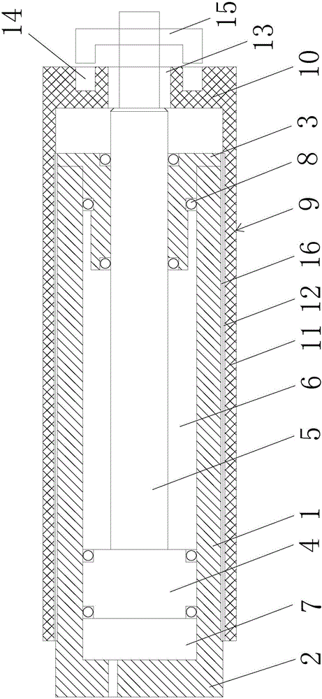
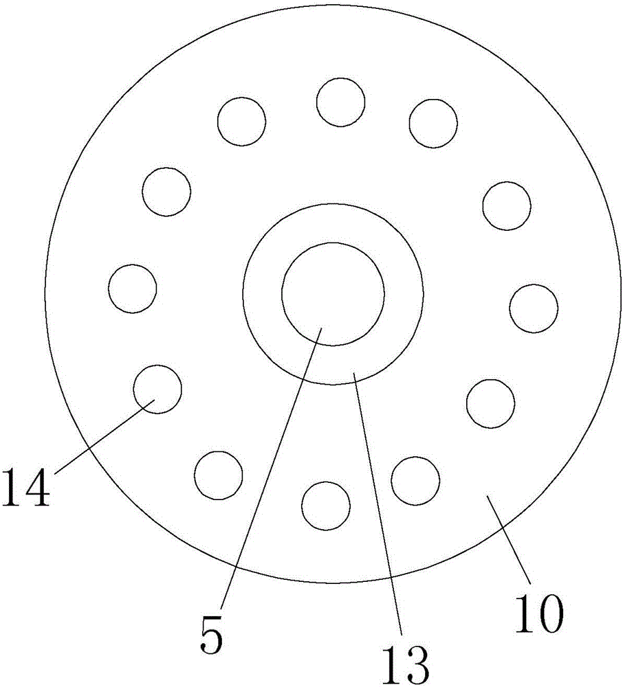
[0022] Such as figure 1 As shown, the hydraulic cylinder in this embodiment includes a cylinder body 1, the cylinder body 1 is cylindrical, and the outer surface of the cylinder body 1 is provided with external threads 16; the two ends of the cylinder body 1 are the cylinder bottom 2 and the cylinder head respectively. 3; the cylinder body 1 is provided with a piston 4 and a piston rod 5, one end of the piston rod 5 is fixed to the piston 4, and the other end ...


PUM


Abstract

The invention proposes a hydraulic cylinder. The hydraulic cylinder comprises a cylinder body; two ends of the cylinder body are respectively a cylinder bottom and a cylinder head; a piston and a piston rod are arranged in the cylinder body; one end of the piston rod is fixed with the piston, and the other end of the piston rod extends out of the cylinder head; the cylinder body is divided into a rod cavity and a rodless cavity by the piston; the cylinder body is coated with a cylindrical fixed cylinder; the fixed cylinder has a circular cylinder bottom, and a cylindrical side wall arranged on the cylinder bottom; the cylinder bottom is positioned on the side of the cylinder head, and is rotationally connected with the piston rod for extending out of the cylinder head; the fixed cylinder can axially move along with the piston rod; multiple fixed grooves are formed in the cylinder bottom; a manipulator is arranged on the piston rod for extending out of the cylinder head, and can extend out to accommodate in the fixed grooves; and the outer wall of the cylinder body and the side wall are in threaded connection. Through interaction of threads, the hydraulic cylinder realizes axial fixation of the piston rod without continuously keeping the pressure of the rodless cavity, so that the energy consumption is reduced, and the service life of a hydraulic system is prolonged.

Description

technical field [0001] The invention relates to the field of hydraulic technology, in particular to a hydraulic cylinder. Background technique [0002] During the use of the hydraulic cylinder, it usually needs to stay for a period of time after a single action is completed. For example, after the rodless cavity enters the oil, the piston moves and drives the piston rod to fully extend, in order to ensure continuous strong support for the object on the piston rod , Usually, the rodless chamber will be continuously pressurized to apply continuous hydraulic pressure to the piston, so that the piston rod will stay still, so that the piston rod will not retract into the cylinder under force. [0003] However, there are also certain defects in this way, that is, due to the continuous pressure maintaining of the rodless cavity, the energy consumption is increased to a certain extent. This long-term continuous pressure holding will cause certain damage to the entire hydraulic syst...

Claims


Application Information

Patent Timeline
IPC IPC(8): F15B15/14F15B15/26
CPCF15B15/1423F15B15/26F15B2015/267
Inventor 汪成刚童心仲勇
Owner HEFEI XIELI HYDRAULIC TECH CO LTD
Why Eureka
Try Eureka