
Gear modification method for cycloidal pinwheel transmission device and cycloidal pinwheel transmission device

The technology of a cycloidal pinwheel and a transmission device is applied in the modification of a cycloidal pinwheel transmission device and the field of a cycloidal pinwheel transmission device, and can solve the problems of high processing difficulty, complicated calculation and modification amount, and high dimensional accuracy requirements. Achieve the effect of improving the bearing capacity and transmission accuracy, and the modification method is simple and easy to implement

Inactive Publication Date: 2017-03-22
TONGJI UNIV
View PDF5 Cites 12 Cited by
  • Summary
  • Abstract
  • Description
  • Claims
  • Application Information

AI Technical Summary

Problems solved by technology

These methods are complicated to calculate the amount of modification, require high dimensional accuracy, and are difficult to process. More importantly, these methods cannot be applied to the unfavorable conditions caused by the gap caused by wear in the cycloidal pin wheel transmission process.

Method used

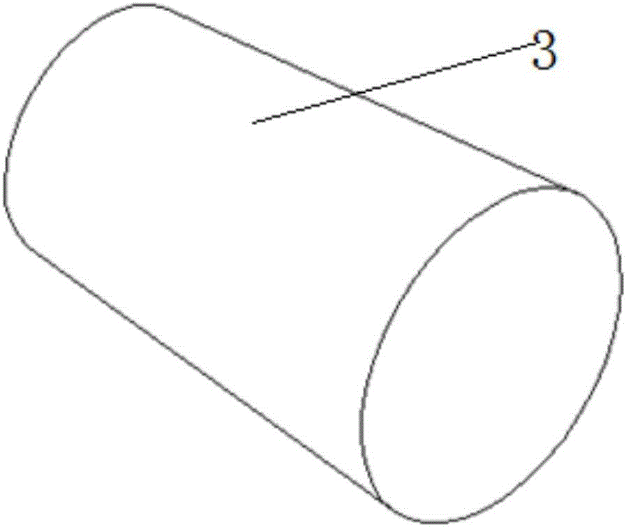
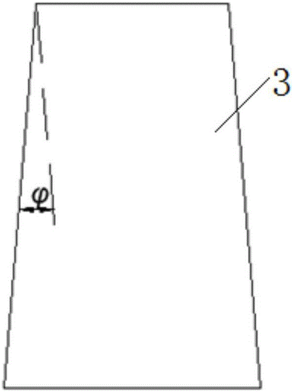
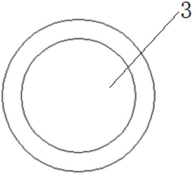

Image

  • Gear modification method for cycloidal pinwheel transmission device and cycloidal pinwheel transmission device
  • Gear modification method for cycloidal pinwheel transmission device and cycloidal pinwheel transmission device
  • Gear modification method for cycloidal pinwheel transmission device and cycloidal pinwheel transmission device

Examples


Embodiment

[0050] A method for modifying the shape of a cycloidal pinwheel transmission, which is used for the cycloidal pinwheel transmission. The traditional cycloidal pinwheel transmission includes a housing, pin teeth and a swing gear. The modification method of the present invention can make the cycloidal needle All the pin teeth in the wheel transmission device are always in contact with the cycloid gear, and can automatically eliminate the backlash caused by work wear, thereby improving the bearing capacity and transmission accuracy of the cycloid pin wheel transmission.

[0051] The cylindrical needle teeth in the traditional cycloidal pinwheel drive are changed to conical needle teeth, and springs and end covers for fixing springs are equipped on the large end faces of each needle tooth;

[0052] Change the horizontal cylindrical surface of the needle groove on the housing in the traditional cycloidal pinwheel transmission to an inclined cylindrical surface;

[0053] Utilizing t...


PUM


Abstract

The invention relates to a gear modification method for a cycloidal pinwheel transmission device and the cycloidal pinwheel transmission device. The cycloidal pinwheel transmission device comprises a shell, a cycloidal gear, pin teeth, springs and an end cap. A pin tooth groove for containing the pin teeth is formed in the inner side wall of the shell. The cycloidal gear is arranged at the center of the shell. The pin teeth are arranged in the pin tooth groove. The pin teeth are in contact with the cycloidal gear and the pin tooth groove at the same time. The pin teeth are circular-truncated-cone-shaped pin teeth. The inner surface of the pin tooth groove is an inclined cylindrical face. The end cap is connected to the shell. The springs are arranged between the big end face of each pin tooth and the end cap. The taper angle phi of each pin tooth satisfies the formula (please see the formula in the specification), wherein mu is the friction coefficient of the surface, in contact with the pin teeth, of the pin tooth groove, and the inclination angle theta of the cylindrical face of the pin tooth groove is equal to the taper angle of the pin teeth. Compared with the prior art, by the adoption of the gear modification method and the cycloidal pinwheel transmission device, the gap defect which is generated between the cycloidal gear and the pin teeth and brought by the manufacturing error and working wear can be made up for, all the pin teeth are made to be kept in contact with the cycloidal gear, and thus the transmission bearing capacity and the transmission accuracy of a cycloidal pinwheel are improved remarkably.

Description

technical field [0001] The invention relates to the field of precision reducers, in particular to a method for modifying a cycloidal pinwheel transmission and the cycloidal pinwheel transmission. Background technique [0002] Cycloidal pinwheel transmission is a device that utilizes cycloidal gears and pin teeth to achieve power transmission. From a geometric point of view, the cycloidal gear is in contact with all the pin teeth; from a mechanical point of view, half of the pin teeth participate in power transmission. Small and many other advantages. At present, cycloidal pinwheel transmission is widely used in high-precision reducers for joints of industrial robots. For example, the RV reducer of Nabtesc Company in Japan uses cycloidal pinwheel transmission. [0003] However, due to manufacturing errors and work wear and tear, not all pin teeth in the actual cycloidal pin gear can contact with the cycloid gear. There is a gap between some pin teeth and the cycloid gear, a...

Claims


Application Information

Patent Timeline
IPC IPC(8): F16H1/32F16H55/08
CPCF16H1/32F16H55/08
Inventor 卜王辉李嘉
Owner TONGJI UNIV
Learn More