

Anti-icing vacuum storage tank
A vacuum gas storage tank and anti-icing technology, which is applied to fixed-capacity gas storage tanks, gas/liquid distribution and storage, pressure vessels, etc., can solve problems such as unfavorable normal production, easy freezing, and abnormal production of equipment. Achieve the effect of improving the anti-freezing effect and avoiding the phenomenon of freezing
Inactive Publication Date: 2017-03-22
十堰冠达汽车零部件有限公司
View PDF0 Cites 0 Cited by
- Summary
- Abstract
- Description
- Claims
- Application Information
AI Technical Summary
Problems solved by technology
[0002] The vacuum gas storage tank in the existing glass production equipment is prone to leakage at the pipe joint. When the temperature is below 0°C, this part is easy to freeze. If this part freezes, the air pipe will be blocked and the equipment will not be able to produce normally.
The existing solution is to bake with an electric stove to maintain the temperature, but some moving parts are difficult to heat, so the effect cannot be achieved, and the operation is difficult, which is not conducive to normal production
Method used
View moreImage
Smart ImageViewing Examples

Examples
Embodiment Construction
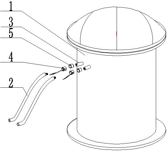
[0010] Such as figure 1 The shown anti-icing vacuum gas storage tank of the present invention includes a tank body 1 and a pipeline 2, and the pipeline 2 is connected to the nozzle 3 of the tank body 1, and the position where the pipeline 2 is connected to the nozzle 3 is provided There is a heating ring 4; the tube mouth 3 is connected with a tube joint 5, and the pipeline is connected to the tube port 3 through the tube joint 5; the outer surface of the tube port 3 is wrapped with an insulating material.
Login to View More PUM
 Abstract
The invention provides an anti-icing vacuum storage tank. The anti-icing vacuum storage tank comprises a tank body and pipelines. The pipelines are connected to pipe openings of the tank body. Heating rings are arranged at the joints of the pipelines and the pipe openings. By adoption of the anti-icing vacuum storage tank, the heating rings are arranged at the joints of the pipelines and the pipe openings so that the temperature of the pipelines can be maintained, the temperature of the joints of the pipelines can be controlled over 0 degree, and thus the icing phenomenon is effectively avoided.
Description
technical field [0001] The invention relates to an air storage tank, in particular to an anti-icing vacuum air storage tank. Background technique [0002] The vacuum gas storage tank in the existing glass production equipment is prone to leakage at the pipe joint. When the temperature is below 0°C, this part is easy to freeze. If this part freezes, the air pipe will be blocked and the equipment will not be able to produce normally. . The existing solution is to bake with an electric stove to maintain the temperature, but some active parts are difficult to heat, so the effect cannot be achieved, and the operation is difficult, which is not conducive to normal production. Contents of the invention [0003] The purpose of the present invention is to provide an anti-icing vacuum gas storage tank, which can solve the problem of freezing of pipelines during load cutting, edging and cleaning of equipment for producing glass products when the temperature is below 0°C. [0004] I...
Claims
Login to View More Application Information
Patent Timeline
 Patent Type & AuthorityApplications(China)
IPC IPC(8): F17C1/00F17C13/10
Inventor彭敏杰张晓枭李友枝
Owner十堰冠达汽车零部件有限公司