Hole-plate type flowmeter hole-plate structure

An orifice structure and flowmeter technology, which is applied to the volume/mass flow generated by mechanical effects, and the detection of fluid flow by measuring differential pressure, which can solve problems such as pipe opening, liquid impact, and reduced measurement accuracy of orifice flowmeters. , to achieve the effect of simple structure and improved measurement accuracy

Inactive Publication Date: 2017-03-22
付建军
View PDF0 Cites 0 Cited by
  • Summary
  • Abstract
  • Description
  • Claims
  • Application Information

AI Technical Summary

Problems solved by technology

In the prior art, since the central hole of the throttling piece is generally arranged in the center of the throttling piece, in this way, during the use of a fluid pipeline that is easy to precipitate liquid, the front end of the throttle piece is easy to accumulate eluate, which makes the pipeline The flow space for the passage of the medium has changed, which not only easily produces the phenomenon of "piping" (severe liquid impact in the pipeline when the medium flow rate is high), but also greatly reduces the measurement accuracy of the orifice flowmeter

Method used


Image

  • Hole-plate type flowmeter hole-plate structure

Examples


Embodiment 1

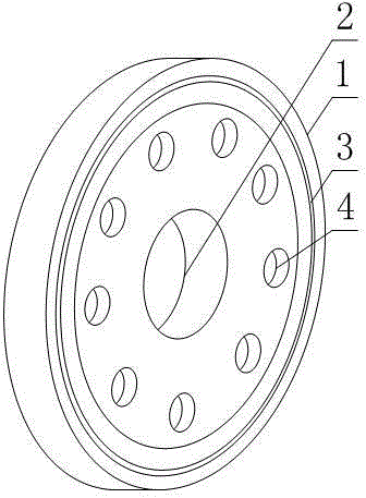
[0018] like figure 1 As shown, an orifice plate structure of an orifice plate flowmeter includes a ring-shaped orifice plate body 1, a circular center hole 2 is provided in the center of the orifice plate body 1, and a circular center hole 2 is arranged outside the orifice plate body 1. The permeable hole 4 between the edge and the central hole 2 passes through both sides of the orifice plate body 1 .

[0019] In this embodiment, the orifice plate body 1 is used for clip-type connection to the pipeline, and the central hole 2 provided is a circulation space for the medium to pass through the orifice plate body 1 . The structure setting of the permeable hole 4 on the orifice body 1 can realize the present invention. During the pressure difference flow metering process of the gaseous fluid that is easy to precipitate the liquid, the precipitated liquid enriched at the front end of the orifice body 1 can be obtained under the pressure difference. The permeable hole 4 flows to th...

Embodiment 2

[0021] The present embodiment is further limited on the basis of embodiment 1, as figure 1 As shown, in order to facilitate the symmetry of the flow velocity of the gaseous fluid at each point on the pipeline cross-section relative to the centerline of the orifice plate body 1, and to facilitate the accuracy of the orifice flowmeter measurement, there are more than one permeable holes 4, and the permeable holes 4 are in the The orifice plate body 1 is evenly distributed in a ring shape relative to the center line of the orifice plate body 1 .

[0022] In order to facilitate the static sealing effect between the orifice plate body 1 and the corresponding connecting flange, both sides of the orifice plate body 1 are provided with annular tenons and grooves 3 .

[0023] In order to weaken the impact of the friction between the impurity and the orifice plate body 1 on the shape of the central hole 2 and the permeable hole 4 when the gaseous fluid contains impurities, and to benefi...


PUM


Abstract

The invention discloses a hole-plate type flowmeter hole-plate structure. The hole-plate type flowmeter hole-plate structure comprises an annular hole-plate body, and a circular center hole is formed in then center of the hole-plate body. The hole-plate type flowmeter hole-plate structure further comprises a water permeable hole which is formed between the external rim of the hole-plate body and the center hole, and the water permeable hole penetrates through two sides of the hole-plate body. According to the hole-plate type flowmeter hole-plate structure, when the hole-plate type flowmeter hole-plate structure is used in the measuring process of differential pressure flow of gaseous fluid from which liquid is easy to be separated out, the purposes of avoiding gathering of separated out liquid at the front end place of the hole-plate body of a pipeline and improving measurement accuracy of the hole-plate type flowmeter can be achieved.

Description

technical field [0001] The invention relates to the field of fluid conveying pipe fittings, in particular to an orifice plate structure of an orifice flowmeter. Background technique [0002] The orifice flowmeter is a non-scale flow measuring device. It is used in conjunction with a pneumatic or electric differential pressure transmitter or a double bellows differential pressure transmitter. Usually, the transmitter converts the differential pressure signal into a proportional output signal. , and then the measured flow is recorded, indicated or regulated by the secondary instrument or regulator. The principle of the orifice flowmeter is to install a throttling member such as an orifice plate or a nozzle inside the pipe. Since the diameter of the throttling member is smaller than the inner diameter of the pipe, when the fluid flows through the throttling member, the flow section suddenly shrinks and the flow speed increases. The static pressure of the fluid at the rear end ...

Claims


Application Information

Patent Timeline
Patent Type & Authority Applications(China)
IPC IPC(8): G01F1/42
Inventor 付建军
Owner 付建军
Why Eureka
Try Eureka