
Pressurizing fatigue test device for large-capacity cavity or semi-enclosed cavity

A fatigue test, semi-closed technology, applied in measuring devices, using repetitive force/pulse force testing material strength, instruments, etc., can solve the problems of low loading rate and large measurement error, and achieve increased inflation and improved discharge. The effect of improving gas efficiency and improving the rate of inflation and deflation

Pending Publication Date: 2017-03-22
JIANGXI HONGDU AVIATION IND GRP
View PDF22 Cites 3 Cited by
  • Summary
  • Abstract
  • Description
  • Claims
  • Application Information

AI Technical Summary

Problems solved by technology

[0007] The present invention aims to solve technical problems such as low loading rate, large measurement error, and closed structure test pieces of the existing pressure fatigue test device, and provides a pressure fatigue test device with a large volume cavity or a semi-closed cavity , to achieve rapid inflation and deflation, the semi-closed cavity (that is, the cavity composed of a semi-closed structure and tooling, with a separation surface) has a slight air leakage, and has a double-effect control mode, which greatly improves the test pressure measurement accuracy

Method used


Image

  • Pressurizing fatigue test device for large-capacity cavity or semi-enclosed cavity

Examples


Embodiment Construction

[0021] The embodiments will be described in detail below in conjunction with the accompanying drawings.

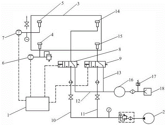
[0022] See attached figure 1 A pressure fatigue test device for a large-volume cavity or a semi-closed cavity includes a computer 1, an air compressor 2, a dual-channel measurement system, a dual-channel inflation and deflation control system, and a vacuum system. The computer 1 is connected to the test piece 3 through a dual-channel measurement system, the front end of the dual-channel inflation and deflation control system is connected to the air compressor 2, and the rear end is connected to the vacuum system. The air control system inflates and deflates the test piece 3.

[0023] The dual-channel measuring system includes pressure measuring point A4 and pressure measuring point B5 arranged on the test piece 3, a pressure sensor A6 and a pressure sensor B7, and the pressure sensor A6 is installed on the pressure measuring point A4 and connected with the computer 1 to f...


PUM


Abstract

The invention provides a pressurizing fatigue test device. The pressurizing fatigue test device comprises a computer, an air compressor, a dual-channel measuring system, a dual-path gas charging-discharging control system and a vacuum system, wherein the front end of the dual-path gas charging-discharging control system is connected with the air compressor; the rear end of the dual-path gas charging-discharging control system is connected with the vacuum system; the dual-channel measuring system comprises dual channels formed by a pressure measuring point A, a pressure sensor A, a computer and a pressure measuring point B, a pressure sensor B and a computer; the dual-path gas charging-discharging system comprises a control loop A formed by an air compressor, a gas charging pipeline A, a pneumatic control valve A, a gas charging-discharging nozzle A, a gas discharging pipeline A and a vacuum system, and a control loop B formed by an air compressor, a gas charging pipeline B, a pneumatic control valve B, a gas charging-discharging nozzle B, a gas discharging pipeline B and a vacuum system. By adopting the pressurizing fatigue test device, the gas charging-discharging efficiency is increased, pressure measurement and the gas charging-discharging nozzles are distributed optimally, the pressure measuring accuracy is increased, and the turbulence degree of gas flow in a gas charging process is lowered; a dual-effect control mode is applied, so that the accuracy and security are improved greatly.

Description

technical field [0001] The invention belongs to the technical field of pressurized fatigue tests, and in particular relates to a pressurized fatigue test device for semi-closed cavities such as large-volume cavities or aircraft hatch covers, fuselage sections, and wall panels. Background technique [0002] The existing pressurized fatigue test system usually adopts the pressurized form of static test: a control center computer, a single point control substation, a pressure sensor and a small inner diameter pipeline (φ10~φ20mm). When loading, the control center issues an inflation command, opens the air inlet of the air control valve, loads through a single channel with a small inner diameter, and feeds back the pressure value to the control center; after the pressure value reaches the set value, the control center issues a pressure release command to open the air Control valve vent port and adopt natural venting mode (direct discharge to atmosphere) for single channel pressu...

Claims


Application Information

Patent Timeline
Patent Type & Authority Applications(China)
IPC IPC(8): G01N3/36
CPCG01N3/36G01N2203/0232G01N2203/0234G01N2203/0073G01N2203/0046G01N2203/0019G01N2203/0005
Inventor 任锋亮刘国祥郑甜王华平许广明黄鹏李鸿岳宝成熊志辉余建波刘庆彬
Owner JIANGXI HONGDU AVIATION IND GRP
Learn More