Data fusion method and data fusion system for laser radar and depth camera

A technology of laser radar and depth camera, which is applied in the field of data fusion, can solve the problems of low precision, narrow field of view of depth camera, unfavorable application of mobile device positioning and obstacle avoidance, etc., and achieve the effect of expanding the detection range and improving the accuracy of information

Active Publication Date: 2017-03-22
BEIJING UNISROBO TECH CO LTD
View PDF4 Cites 24 Cited by
  • Summary
  • Abstract
  • Description
  • Claims
  • Application Information

AI Technical Summary

Problems solved by technology

However, the field of view of the depth camera is narrow, there is a blind area for a very short distance, and the accuracy is low, which is very unfavorable for the positioning and obstacle avoidance of mobile devices; the laser radar can only obtain points on one or several planes, and when placed horizontally, it is difficult for other Objects with high heights cannot be detected, so the obstacle avoidance function cannot be realized independently

Method used


Image

  • Data fusion method and data fusion system for laser radar and depth camera
  • Data fusion method and data fusion system for laser radar and depth camera
  • Data fusion method and data fusion system for laser radar and depth camera

Examples


Embodiment 1

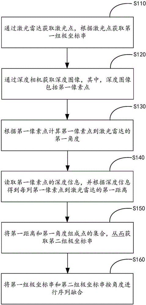
[0053] figure 1 It is a flow chart of the data fusion method of the laser radar and the depth camera provided by Embodiment 1 of the present invention.

[0054] refer to figure 1 , the method includes:

[0055] Step S110, obtaining the laser point through the laser radar, and obtaining the first set of polar coordinate strings according to the laser point;

[0056] Specifically, when the lidar scans by rotating a single point, it can obtain a series of points on a horizontal plane or multiple horizontal planes around 360°; when it uses a static scanning method, it can obtain a series of points on one horizontal plane or multiple horizontal planes , the angle cannot reach 360°, but the accuracy is higher; when the laser radar is installed, it must be kept parallel to the horizontal plane to ensure that the acquired laser points are parallel to the horizontal plane; the first set of polar coordinate strings is represented by Q 1 , Q 2 , Q 3 ,...Q n Represents; in addition,...

Embodiment 2

[0094] Figure 5 It is a schematic diagram of the data fusion system of the laser radar and the depth camera provided by the second embodiment of the present invention.

[0095] refer to Figure 5 , the data fusion system of laser radar and depth camera, comprising: laser radar 100, depth camera 300 and data fusion module 200;

[0096] The laser radar 100 is used to obtain laser points, and obtain the first set of polar coordinate strings according to the laser points;

[0097] A depth camera 300, configured to acquire a depth image, wherein the depth image includes a first pixel point, calculate a first angle from the first pixel point to the laser radar 100 according to the first pixel point, read the depth information of the first pixel point, and According to the depth information, the first distance from the first pixel point in each column to the laser radar 100 is obtained, and the first distance and the first angle are formed into a set of points, thereby obtaining a...


PUM


Abstract

The invention provides a data fusion method and a data fusion system for a laser radar and a depth camera, wherein the method and the system relate to the technical field of data fusion. The method comprises the steps of acquiring a laser point by means of the laser radar, acquiring a first set of polar coordinate strings according to the laser point; acquiring a depth image by means of the depth camera, wherein the depth image comprises a first pixel; calculating a first angle between the first pixel and the laser radar according to the first pixel; reading depth information of the first pixel, and obtaining a first distance between each row of first pixels and the laser radar according to the depth information; combining the first distance and the first angle for forming a point set, thereby obtaining a second set of polar coordinate strings; and performing sequence fusion on the first set of polar coordinate strings and the second set of polar coordinate strings. The data fusion method and the data fusion system can enlarge detection range and improve information precision through data fusion.

Description

technical field [0001] The invention relates to the technical field of data fusion, in particular to a data fusion method and system of a laser radar and a depth camera. Background technique [0002] Both depth cameras and lidar can be used for navigation and obstacle avoidance in mobile devices. However, the field of view of the depth camera is narrow, there is a blind area for a very short distance, and the accuracy is low, which is very unfavorable for the positioning and obstacle avoidance of mobile devices; the laser radar can only obtain points on one or several planes, and when placed horizontally, it is difficult for other Objects at high altitudes cannot be detected, so the obstacle avoidance function cannot be realized independently. Contents of the invention [0003] In view of this, the object of the present invention is to provide a data fusion method and system for laser radar and depth camera, so as to expand the detection range and improve the information ...

Claims


Application Information

Patent Timeline
Patent Type & Authority Applications(China)
IPC IPC(8): G01S17/02
CPCG01S17/86
Inventor 刘雪楠沈刚
Owner BEIJING UNISROBO TECH CO LTD
Why Eureka
Try Eureka