
Indicator diagram identification method and device

A recognition method and dynamometer technology, which are applied in character and pattern recognition, instruments, computer parts, etc., can solve the problems of low recognition accuracy and low recognition efficiency, and achieve low recognition accuracy and low recognition efficiency. Effect

Inactive Publication Date: 2017-03-22
PETROCHINA CO LTD
View PDF9 Cites 4 Cited by
  • Summary
  • Abstract
  • Description
  • Claims
  • Application Information

AI Technical Summary

Problems solved by technology

[0005] Embodiments of the present invention provide a method and device for identifying dynamometer diagrams, by using the gradient direction histogram of dynamometer diagrams to identify the type of dynamometer diagrams, so as to solve the problems of low recognition accuracy and recognition efficiency in existing recognition methods low technical issues

Method used


Image

  • Indicator diagram identification method and device
  • Indicator diagram identification method and device
  • Indicator diagram identification method and device

Examples


Embodiment Construction

[0052] In order to make the objectives, technical solutions and advantages of the present invention clearer, the present invention will be further described in detail below with reference to the embodiments and accompanying drawings. Here, the exemplary embodiments of the present invention and their descriptions are used to explain the present invention, but not to limit the present invention.

[0053] Considering the existing dynamometer identification methods, in the process of feature extraction, due to the limitations of the method itself, generally only some primary feature quantities can be extracted, and these primary feature quantities are used to identify the dynamometer diagram. The accuracy of the results is often not high. At the same time, because most of the existing methods need to process according to the original data of the dynamometer, and different dynamometer acquisition methods and processing and storage methods are different, the corresponding processing...


PUM


Abstract

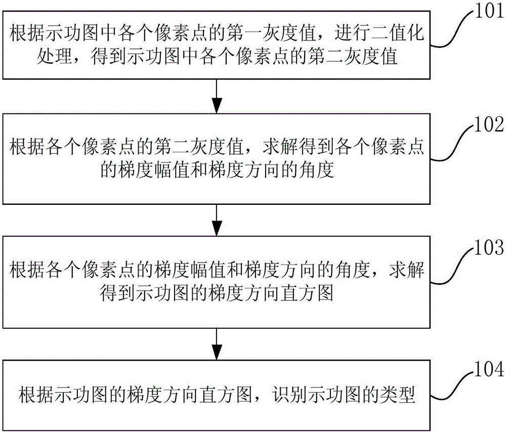
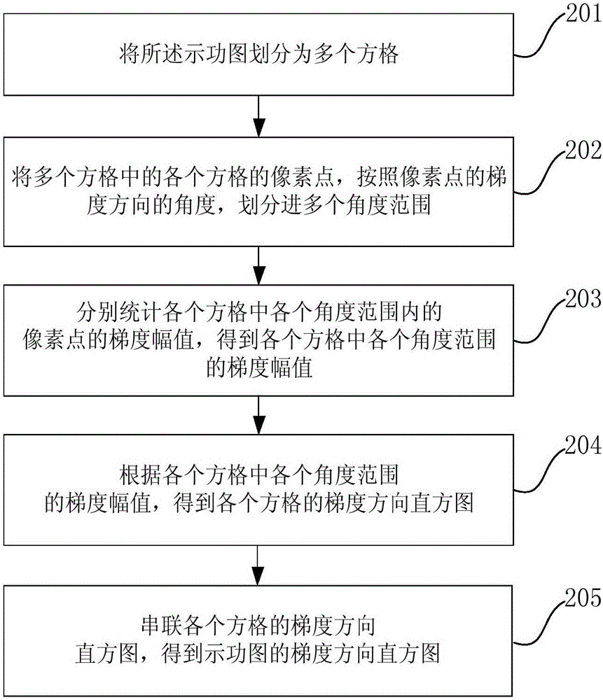
The invention provides an indicator diagram identification method and device. The method comprises according to first gray values of pixel points of an indicator diagram, second gray values of the pixel points are obtained by binarization; according to the second gray values of the pixel points, the gradient amplitude and the angle in the gradient direction of each pixel point are obtained; according to the gradient amplitudes and the angles, in the gradient direction, of the pixel points, a histogram, in the gradient direction, of an indicator diagram is obtained; and according to the a histogram, in the gradient direction, of the indicator diagram, the type of the indicator diagram is identified. According to the invention, the type of the indicator diagram is identified by utilizing the histogram, in the gradient direction, of the indicator diagram, the technical problem that a present identification method is low in identification efficiency and accuracy is solved, and the identification speed and accuracy are improved; and the histogram in the gradient direction can be obtained directly according to a graph of the indicator diagram, rely on original data is avoided, and the identification accuracy is further improved.

Description

technical field [0001] The invention relates to the technical field of oil and gas production, in particular to a method and device for identifying a dynamometer diagram. Background technique [0002] In the process of oil and gas production, the dynamometer diagram can be a closed curve formed by the relationship between the load and the displacement, which can reflect the working state of the pumping unit. Therefore, the dynamometer diagram can be an important basis for oil and gas production management. According to the type of dynamometer diagram and other information, the working condition of the pumping unit can be diagnosed, and then the working state of the oil well can be quickly grasped, and the parameters of the oil well can be analyzed and judged whether the parameters are reasonable. Adjust oil wells in a timely manner to reduce losses and increase oil and gas production. [0003] Since the dynamometer diagram plays an important role in the specific oil and ga...

Claims


Application Information

Patent Timeline
IPC IPC(8): G06K9/38G06K9/46
CPCG06V10/28G06V10/507
Inventor 胥小马李金诺龚仁彬汤林李群
Owner PETROCHINA CO LTD
Learn More