Full-automatic magnetization and demagnetization equipment for rotary inductive locating of magnetic rings
An induction positioning and fully automatic technology, applied in the direction of magnetic objects, rotary conveyors, conveyors, etc., can solve the problems of long production process time, extremely poor quality of polar angle, low production efficiency, etc., and achieve product quality improvement and efficiency high effect
- Summary
- Abstract
- Description
- Claims
- Application Information
AI Technical Summary
Problems solved by technology
Method used
Image
Examples
Embodiment 1
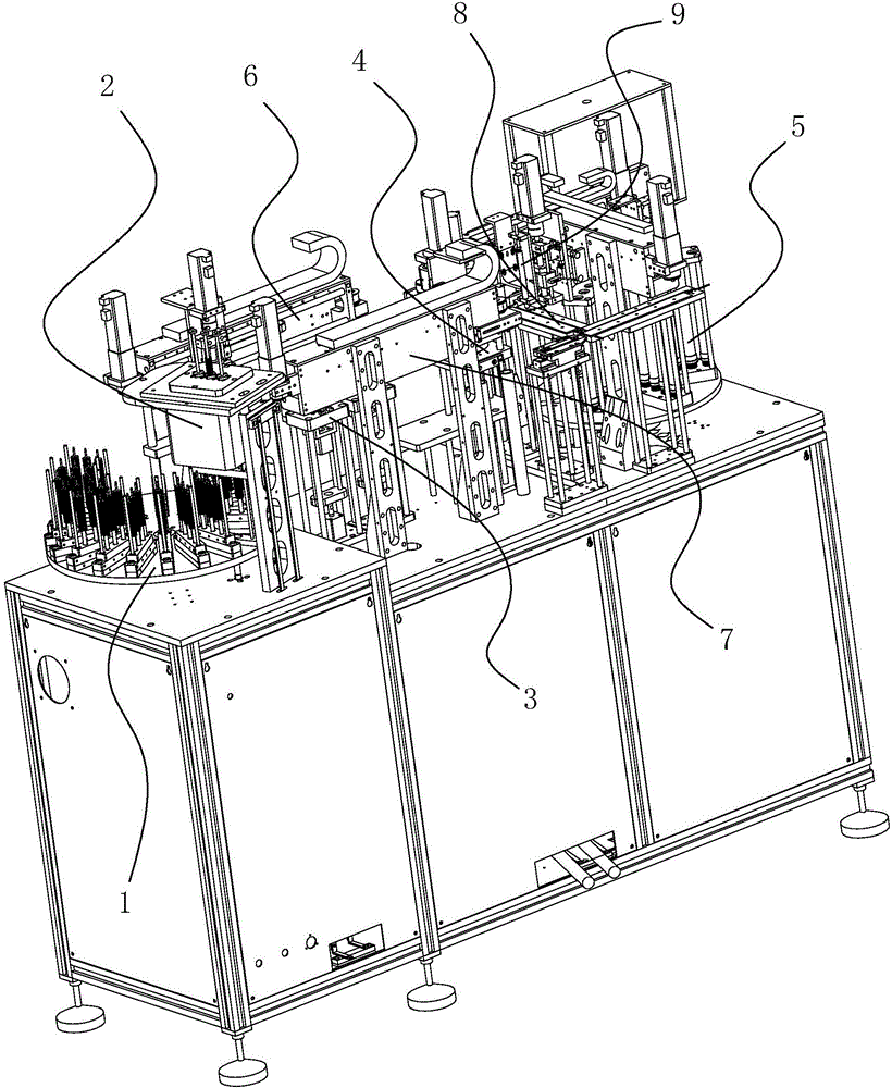
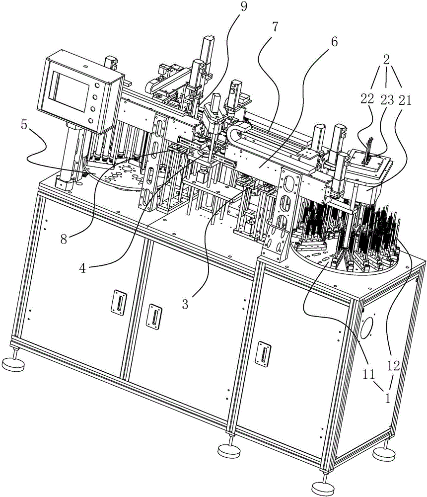
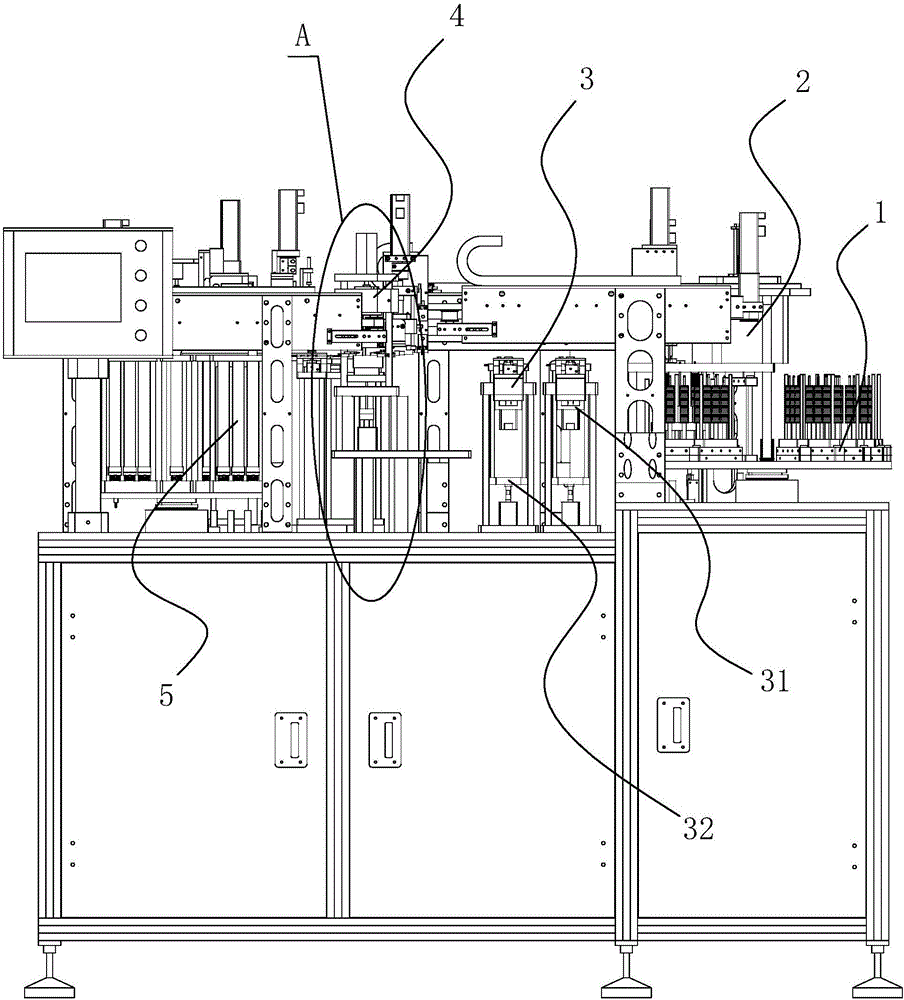
[0026] like Figure 1-Figure 5 As shown, a fully automatic charging and degaussing equipment for magnetic ring rotation induction positioning, including a rotating material table 1 for preventing the magnetic ring, a degaussing assembly 2 for removing the original magnetism of the magnetic ring, and a degaussing assembly for demagnetizing the demagnetized The rotation angle correction assembly 3 for rotating and positioning the ring, the magnetizing assembly 4 for making the magnetic ring magnetic after the rotation positioning, the collecting assembly 5 for storing the magnetized magnetic ring, and transporting the magnetic ring on the rotating material table 1 to The first displacement assembly 6 on the angle correction assembly 3, the second displacement assembly 7 that transports the magnetic ring on the rotation angle correction assembly 3 to the magnetization assembly 4, and the magnetic ring on the magnetization assembly 4 to the collection assembly The third shifting a...
Embodiment 2
[0029] like Figure 1-Figure 5 As shown, a fully automatic charging and degaussing equipment for magnetic ring rotation induction positioning, including a rotating material table 1 for preventing the magnetic ring, a degaussing assembly 2 for removing the original magnetism of the magnetic ring, and a degaussing assembly for demagnetizing the demagnetized The rotation angle correction assembly 3 for rotating and positioning the ring, the magnetizing assembly 4 for making the magnetic ring magnetic after the rotation positioning, the collecting assembly 5 for storing the magnetized magnetic ring, and transporting the magnetic ring on the rotating material table 1 to The first displacement assembly 6 on the angle correction assembly 3, the second displacement assembly 7 that transports the magnetic ring on the rotation angle correction assembly 3 to the magnetization assembly 4, and the magnetic ring on the magnetization assembly 4 to the collection assembly The third shifting a...
Embodiment 3
[0033] like Figure 1-Figure 5 As shown, the rotary material table 1 includes a turntable 11 and several vertical rods 12 uniformly distributed on the turntable 11 along the radial direction of the turntable 11 . The magnetic ring is set on the vertical rod 12, and the rotating disk 11 is driven by a motor to rotate. The motor is preferably a stepping motor. It is necessary to provide the static time for the degausser 21 to act on the magnetic ring. The degausser 21 is preferably provided with a corresponding magnetic ring outer contour. The inner cavity is used to increase the degaussing speed.
[0034] The clamping and lifting assembly in Embodiment 1 has the following embodiments:
PUM
 Abstract
Description
Claims
Application Information
 - R&D
- Intellectual Property
- Life Sciences
- Materials
- Tech Scout
- Unparalleled Data Quality
- Higher Quality Content
- 60% Fewer Hallucinations
Browse by: Latest US Patents, China's latest patents, Technical Efficacy Thesaurus, Application Domain, Technology Topic, Popular Technical Reports.
© 2025 PatSnap. All rights reserved.Legal|Privacy policy|Modern Slavery Act Transparency Statement|Sitemap|About US| Contact US: help@patsnap.com


